What you are building
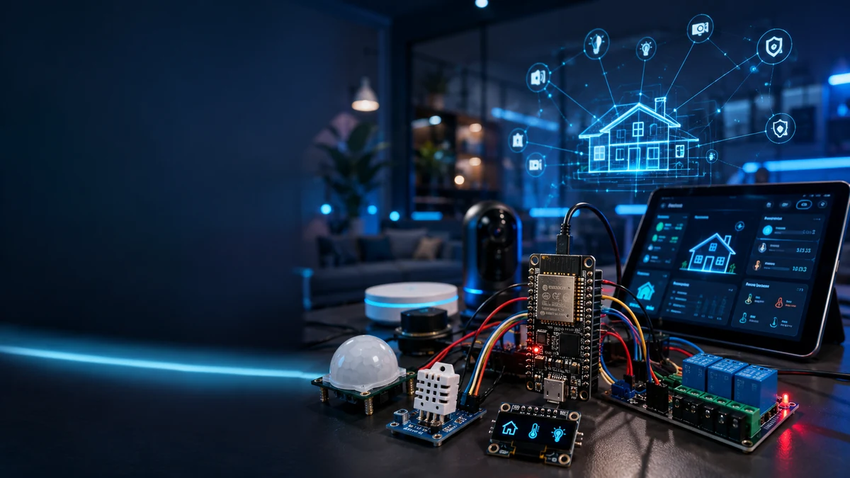
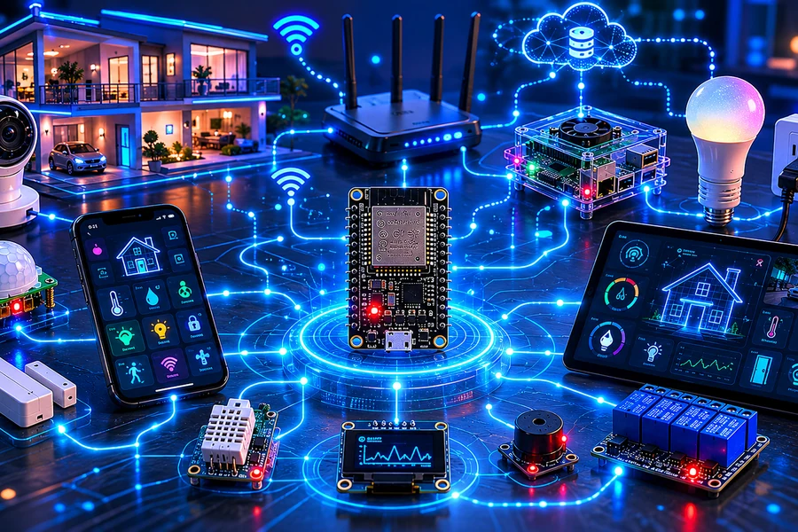
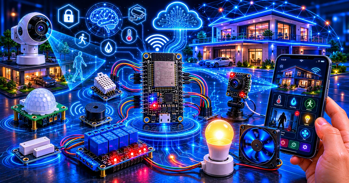
This is not another tiny blinking LED project. You are building a real IoT control system: sensors feed the ESP32, the ESP32 publishes events, a dashboard displays status, and automation rules decide what happens next.
Parts needed
Controller
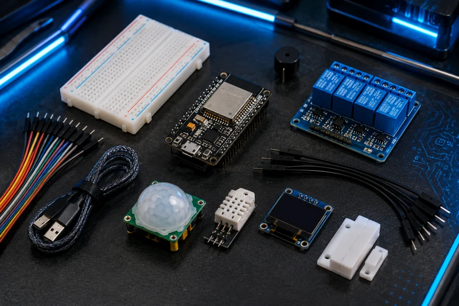
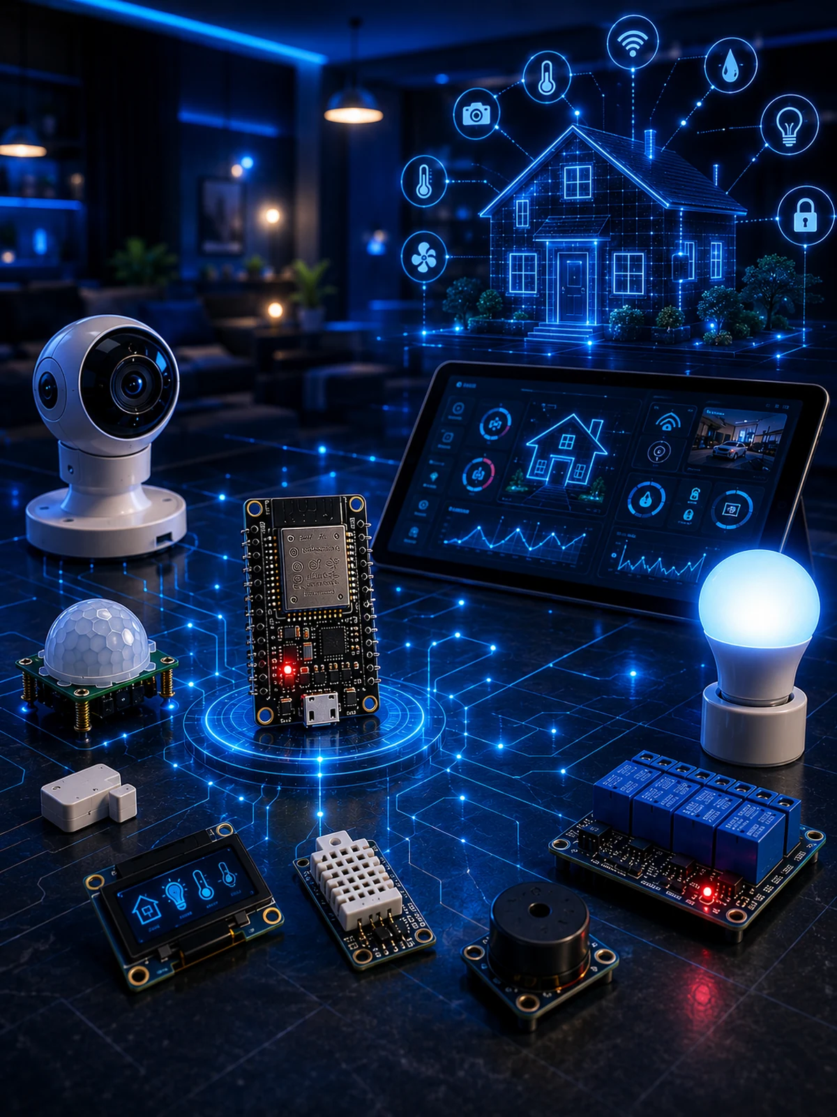
ESP32 Dev Board, USB cable, breadboard, jumper wires, and a stable USB power source.
Sensors
DHT22, PIR motion sensor, magnetic reed/door sensor, optional LDR light sensor, and resistors.
Outputs
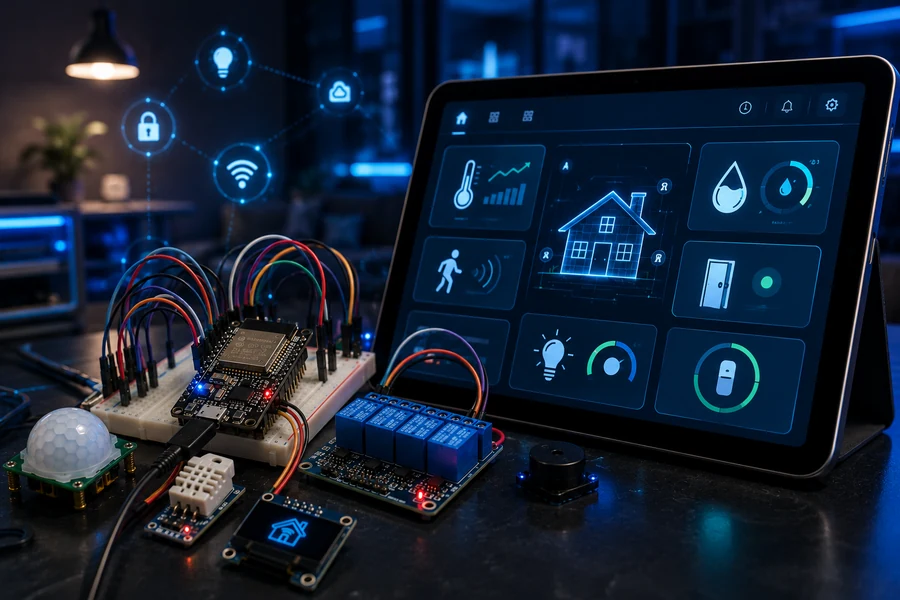
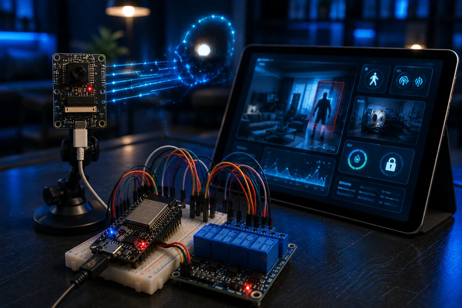
OLED display, low-voltage relay module, buzzer, LED/smart light demo load, and optional ESP32-CAM node.
Wire the ESP32 smart-home hub
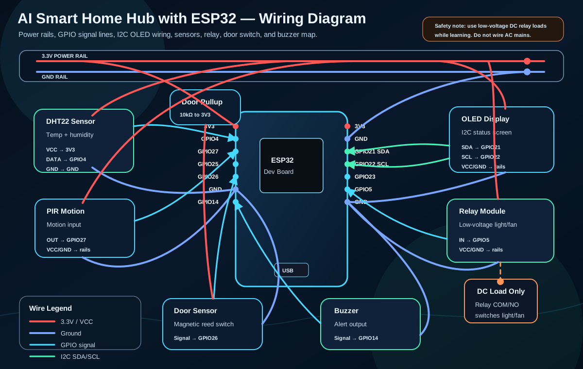
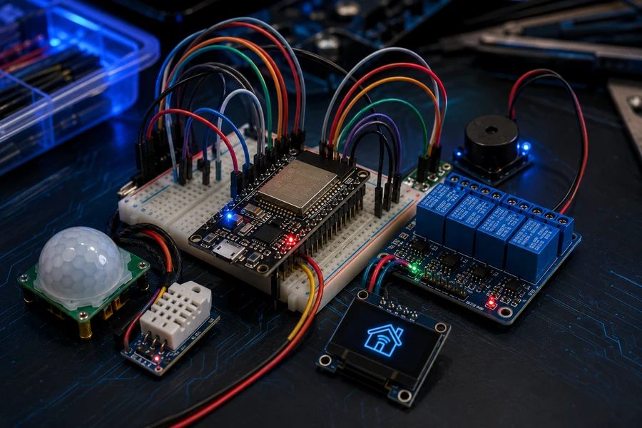
Start with clean power rails, then connect one module at a time. Do not connect every sensor at once and then wonder why the project is dead. That is how beginners bury themselves.
| Module | ESP32 Pin | Purpose |
|---|---|---|
| DHT22 | GPIO 4 | Temperature and humidity data |
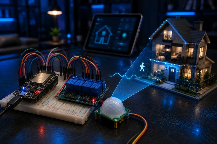
| PIR Motion | GPIO 27 | Motion detection |
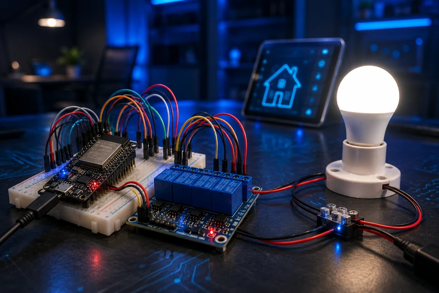
| Relay IN | GPIO 5 | Low-voltage light/fan control |
| Door Sensor | GPIO 14 | Open/closed state |
| OLED SDA/SCL | GPIO 21 / GPIO 22 | I2C display status |
| Buzzer | GPIO 26 | Local warning output |
Test hardware before adding the network
First confirm the DHT22 readings in the serial monitor. Then test the PIR. Then test the relay with a safe LED or low-voltage lamp. Only after that should you add MQTT, dashboard tiles, and phone alerts.
Add MQTT network flow
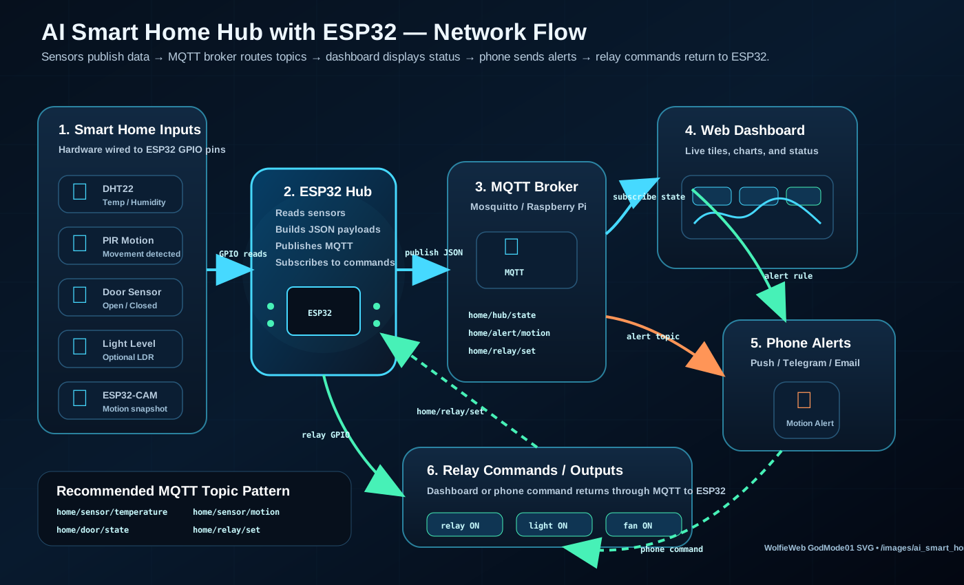
The ESP32 should publish sensor states to an MQTT broker. The dashboard subscribes to those topics and shows the current home status. Phone alerts trigger when motion, heat, or door events cross your rule limits.
- home/motion — PIR status
- home/temp — DHT22 temperature and humidity
- home/door — open/closed state
- home/relay/set — relay command from dashboard
- home/alert — phone alert events
Build the dashboard like a control panel
Your dashboard should show motion, temperature, humidity, door state, light level, relay state, and alert history. Keep the buttons large and obvious. A dashboard that looks cool but confuses the reader is not helping them.
Create the automation rules engine
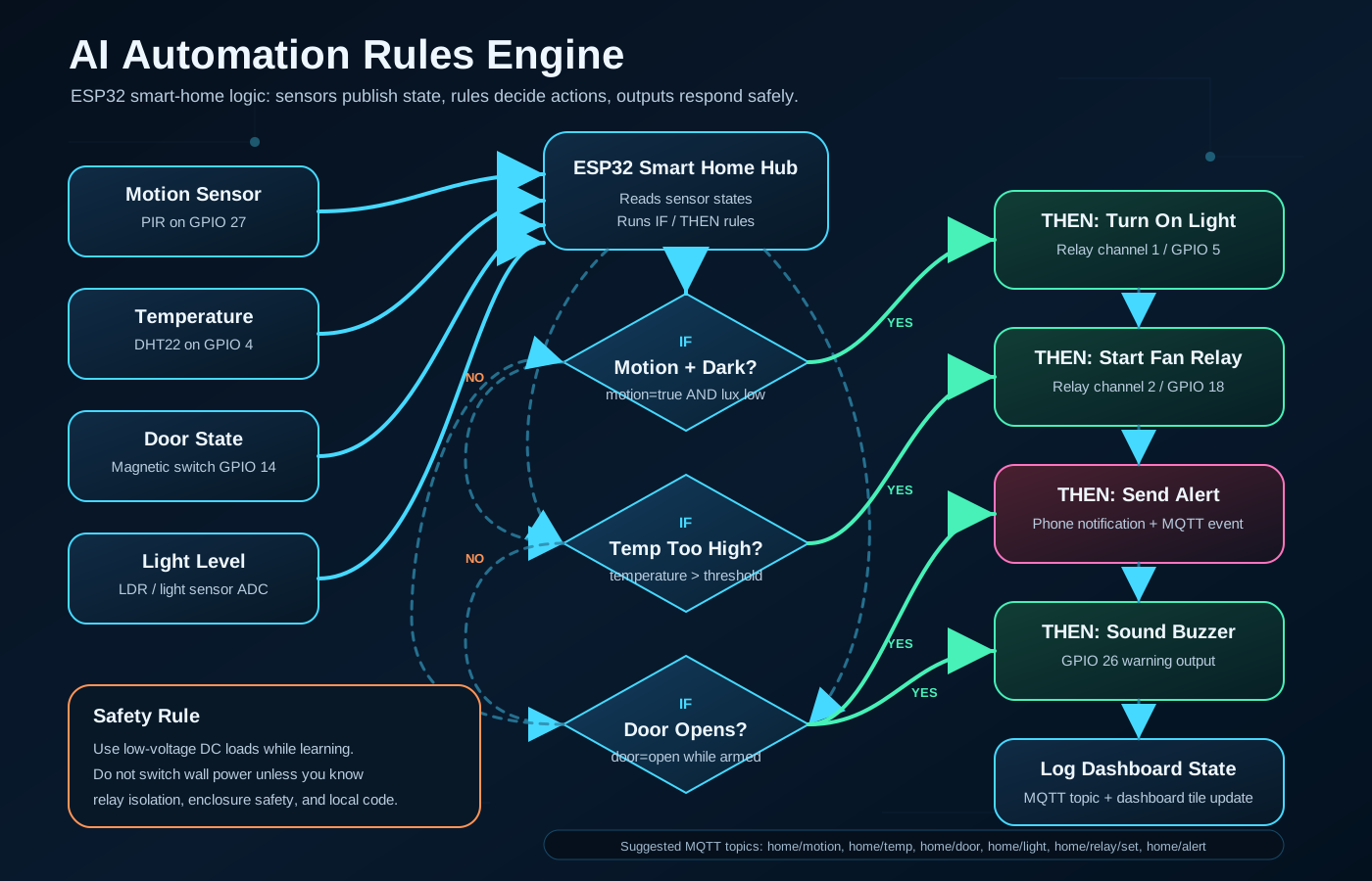
This is where the project becomes advanced. The ESP32 watches conditions and reacts. The logic stays simple enough for a reader to understand, but powerful enough to feel like a real smart-home system.
// Example rule logic
IF motion_detected AND room_is_dark
THEN turn_on_light_relay

IF temperature > 80F
THEN turn_on_fan_relay AND send_alert

IF door_open AND system_armed
THEN sound_buzzer AND publish home/alert
Make the home react intelligently
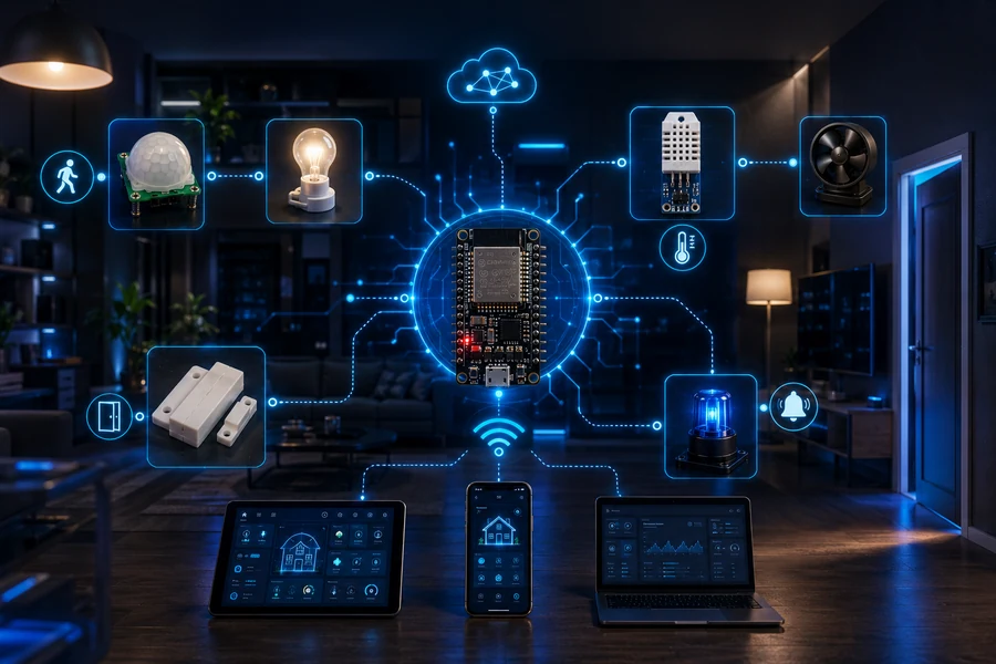
Motion can trigger light. Temperature can trigger a fan relay. A door event can trigger a phone alert. This is the difference between a connected gadget and a connected system.
Build gallery
Video lightbox section
These video cards open in a lightbox so the reader stays on your page. If YouTube blocks an embed, each card also includes a direct “Open on YouTube” fallback link.
Reader takeaway
When this project is finished, the reader understands more than wiring. They understand how an IoT system thinks: sensors create events, MQTT moves messages, dashboards show state, and automation rules trigger action.
⚡ Shop ESP32 Starter Kits