A hidden magnet. Two moving axes. A message that glides across the board.
Build a Raspberry Pi + ESP32 magnetic message-board prototype, one tested stage at a time.
Try the interactive previewClick to enlarge · AI concept illustration, not a tested build photo
This browser preview shows the planned route. It never connects to motors. The physical board moves slowly, pauses on each letter and glides across intermediate letters.
Type up to 32 letters and spaces.
Type a word in a Raspberry Pi browser. The Pi converts letters into coordinates and sends them over USB. An ESP32 drives two independent belt axes under a thin board. A hidden magnet pulls a lightweight token across the letters.
Check the route before powering motors.
Verify origin, direction and measured distance.
Add the token and spell your first message.
Inspired by Kat Shann’s OuijaCNC writeup. WolfieWeb’s code, layout and Cartesian reference design are separate. No microphone, AI response generation, or automatic homing is included.
| Part | Reference choice | Important detail |
|---|---|---|
| Host + controller | Pi 3 B+ or newer; original ESP32-WROOM DevKit | Pi runs the interface; ESP32 produces step pulses. |
| Motion | Two independent belt axes, two 200-step/rev bipolar motors, GT2 20-tooth pulleys | 2 mm belt pitch; 1/16 microstepping. Not a CoreXY belt path. |
| Drivers | Two Pololu DRV8825 #2133 carriers | Match the documented pin labels and current-limit procedure. |
| Power + stop | Enclosed 12 V 3 A supply; fuse and DC-rated cut-off; NC signal stop | USB powers logic. Motor power stays separate; grounds join. |
| Protection | Two 100 µF / 35 V electrolytic capacitors; two 10k pull-ups | One capacitor at each VMOT input. Pull up ENBL and GPIO32. |
| Mechanism + surface | 180 × 120 mm minimum clear travel; thin acrylic; captive magnets; lightweight token | Software envelope is 160 × 100 mm. No CAD fabrication files supplied. |
Mechanical assembly requires an existing Cartesian gantry or fabrication experience. Follow your rails’ assembly drawings. Secure the upper token’s magnets and reduce friction before increasing magnetic force.
For the original ESP32-WROOM DevKit and the specified DRV8825 carriers. GPIO numbers are not header positions. Remove power before wiring or changing motor connections.
| Signal | Connect to |
|---|---|
| X driver STEP / DIR | GPIO25 / GPIO26 |
| Y driver STEP / DIR | GPIO27 / GPIO14 |
| Both ENBL | GPIO13, plus shared 10k pull-up to 3V3 |
| Both RESET and SLEEP | ESP32 3V3 |
| Both MODE0 / MODE1 / MODE2 | GND / 3V3 / GND (1/16 step) |
| Each VMOT / GND | Protected 12 V positive / motor ground; common ESP32 ground |
| Each motor | One measured coil pair A1/A2; other pair B1/B2 |
| Signal stop | GPIO32 → NC contact → GND; 10k from GPIO32 to 3V3 |
| Each decoupling capacitor | 100 µF close to VMOT/GND, observing polarity |
For the specified Pololu carrier only: current limit = 2 × VREF. Start at a 0.5 A limit (VREF 0.25 V) only with motors rated at least 0.5 A per phase. Follow the manufacturer’s measurement instructions. Clone carriers may use different sense resistors.
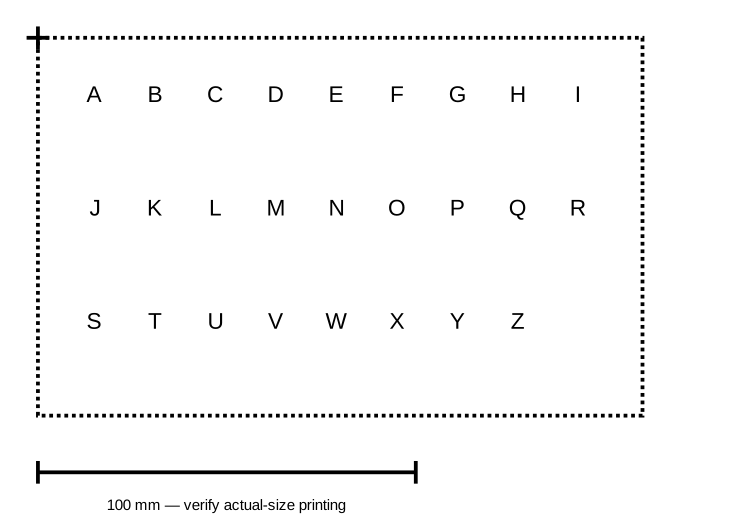
Letter centres: A–I at x15…143 mm in 16 mm increments, y15; J–R on y45; S–Z on y75. Origin is top-left, +X right, +Y downward when viewed from above. The project README includes the full layout and calibration formula.
Expect slow motion: approximately 1 mm/s maximum on the major axis, with no acceleration planner. Software limits cannot detect stalls or an incorrect manual origin. Never leave the mechanism running unattended.
Download actual-size alphabet overlay
Includes the ESP32 sketch, Raspberry Pi Flask controller, simulation mode, letter mapping, setup guide and software tests. This uses a custom serial protocol, not G-code.
Download code + setup guidesudo apt update sudo apt install python3-venv python3 -m venv .venv . .venv/bin/activate python -m pip install -r requirements.txt python -m unittest -v waitress-serve --listen=127.0.0.1:8080 --threads=2 app:app
Run from the extracted project directory. Open http://127.0.0.1:8080 on the Pi. The header must say SIMULATION. Use the README’s hardware-mode command only after the wiring checks.
Keep the controller on the Pi. Upload this article to Hostinger; do not upload the controller there. Use an SSH tunnel for a remote browser. Python target: 3.11+; reference packages Flask 3.1.2, pyserial 3.5, Waitress 3.0.2.
These browser checkboxes record no test results and do not persist. Actual measurements must be taken on the physical build.
Buzzing: power off and verify coil pairs and current limit. Wrong scale: check 1/16 straps and pulley pitch before changing steps/mm. Token slips: remove power and reduce surface friction or gap. Wrong direction: change the firmware axis inversion flag, upload again and re-zero. No serial access: close Serial Monitor and verify the device path and dialout permission.
No relevant full-build video has been verified for this original reference design. Hardware footage can be added after a bench build; the interactive route preview above is explicitly a simulation.