Tutorial 03 · Raspberry Pi Robotics

Build a line-following robot with PID control

Turn your Raspberry Pi robot car into a smooth, accurate line follower. Mount and calibrate IR sensors, verify every connection, and tune a Python PID loop that keeps the robot centered on the track.
3–5 sensorsIR reflectance array
Python 3Raspberry Pi control
PID steeringSmoother corrections
IntermediateBuild difficulty
Mission overview

What you’ll build

01

Robot behavior

  • Read a black line with three to five IR sensors.
  • Estimate whether the line is left, centered, or right.
  • Adjust each motor continuously to stay centered.
02

Parts checklist

  • Raspberry Pi robot car and motor driver
  • Three to five IR sensors or a ready-made array
  • Jumper wires, mounting hardware, and black tape
  • Optional MCP3008 for analog sensor arrays
Best starting point: Use three sensors—left, center, and right—and a wide 18–25 mm tape line. Add more sensors only after the basic build follows reliably.
Hardware close-up

See exactly what the sensors are doing

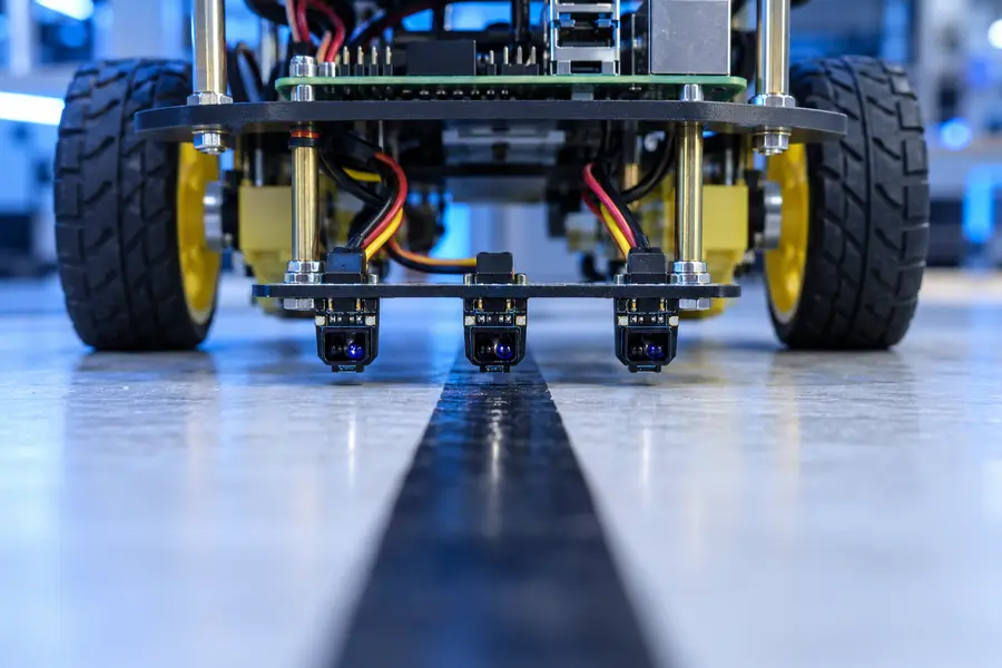
Three IR reflectance sensors mounted over a black line

Mounting targets

  • Position sensors 3–8 mm above the floor.
  • Keep the array centered and perfectly level.
  • Shield sensors from strong direct sunlight.
  • Route wires safely away from the wheels.
GPIO warning: Raspberry Pi inputs accept only 3.3V logic. Level-shift any 5V sensor output.
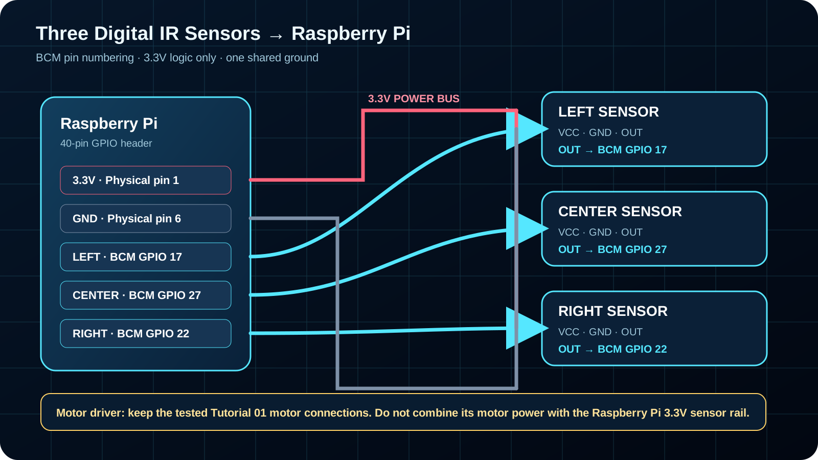
Clear Raspberry Pi wiring map for left, center, and right IR sensors
Clear three-sensor map: LEFT → BCM 17, CENTER → BCM 27, RIGHT → BCM 22, with shared 3.3V power and ground.
Build sequence

From wiring to smooth tracking

Mount

Place the sensor array low, centered, and ahead of the wheels.

Verify

Test every sensor over the floor and line before driving.

Calibrate

Record light and dark readings and choose stable thresholds.

Drive

Confirm left and right motor directions match the code.

Tune

Raise P gradually, add D to reduce weaving, and use I sparingly.

Software launch

Run the Python tools in order

python3 calibrate.py
python3 test_sensors.py
python3 line_following.py

Before the final command

  • Sensor test reports correct left, center, and right states.
  • Motor test confirms forward direction on both sides.
  • The robot is raised safely for the first wheel test.
  • Your driver pins match the Tutorial 01 configuration.
Do not tune PID around a wiring fault. If the robot turns the wrong direction or a sensor never changes state, fix that first.
Choose your sensor

Digital or analog wiring

A

TCRT5000 digital modules

Use three separate sensors with digital DO/OUT pins: LEFT → GPIO 17, CENTER → GPIO 27, and RIGHT → GPIO 22.
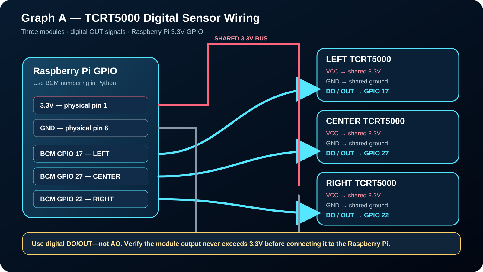
Clear TCRT5000 digital sensor wiring to Raspberry Pi GPIO 17, 27, and 22
B

Analog array through MCP3008

Use this for a QTR-style analog array. The MCP3008 converts analog readings for the Raspberry Pi over SPI.
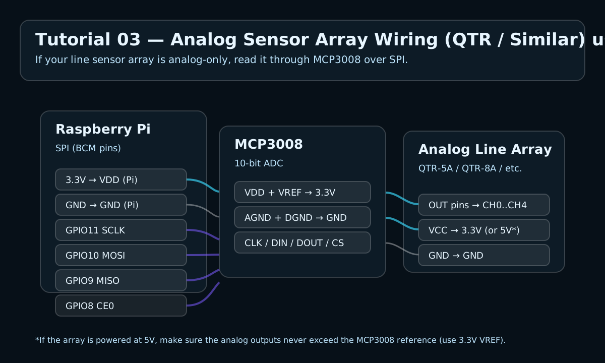
Analog line sensor array wired to Raspberry Pi through MCP3008
Watch and learn

Three supporting video lessons

IR sensor fundamentals

See how sensors distinguish a dark line from a light floor.

PID control explained

Learn how proportional and derivative control steady steering.

Full build walkthrough

Follow mounting, wiring, testing, and troubleshooting.

Keep building

Take Tutorial 03 to your workbench

Save the printable guide or return to the Academy for your next build.

🤖