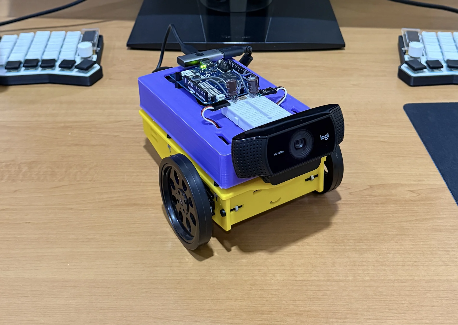
Make the camera control the wheels
The Linux side of UNO Q finds a face in the camera image. Python measures how far that face sits from the centre, then asks the board’s microcontroller to turn the two wheels. It is a practical introduction to the perception → decision → movement loop used in robotics.
DRIVE_BIAS = 0.0 for the first build.Based on Samuel Alexander’s open-source face-following robot. This WolfieWeb guide reorganises the build into testable stages and uses a separate servo power supply. The supplied upstream application is unchanged. Documentation and syntax have been reviewed; this adaptation has not been tested on physical hardware.
Buy the right kind of Arduino
You need an UNO Q. An UNO R3, UNO R4, or ordinary ESP32 cannot run this Linux/App Lab project unchanged. Start by checking what you already own; a compatible webcam and chassis can be reused.
| Part | What to look for |
|---|---|
| 1 × Arduino UNO Q | The source lists 2GB or 4GB; 4GB offers more memory headroom. |
| 1 × USB webcam | UVC-compatible. The creator uses a Logitech C922. |
| 2 × continuous-rotation servos | With matching wheels, accepting 1000–2000 µs control pulses. Ordinary 180° SG90 positional servos are unsuitable. |
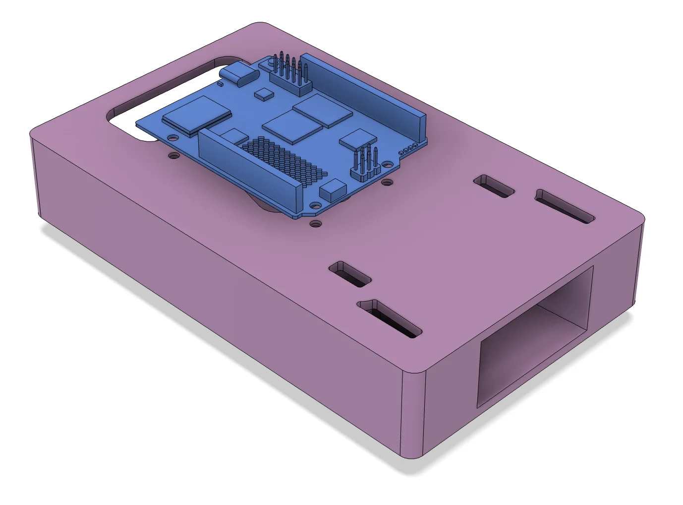
| Chassis + rear caster/skid | Source includes STL files; an equivalent two-wheel platform also works. |
| UNO Q power + USB host connection | A suitable USB-C supply/power bank and a compatible USB-C hub with power delivery and USB-A data. A charging-only splitter will not connect the webcam. |
| Regulated servo power supply | Use 5V-compatible servos and a supply sized for the sum of both stall currents. Check the servo datasheets. Add a switch in the servo supply lead. |
| Wires and power distribution | Secure connectors for motor current, jumper wires for signals and common ground; optional 100 µF, ≥10V capacitor across the servo power rail. |
| Computer + local network | For App Lab setup and the browser dashboard. |
Check the complete parts cost before buying. This is a Linux vision robot, not a cheap UNO starter-kit project. Prices vary; no unverified total is quoted here.
 + Click to enlarge
Two signals. One common ground.
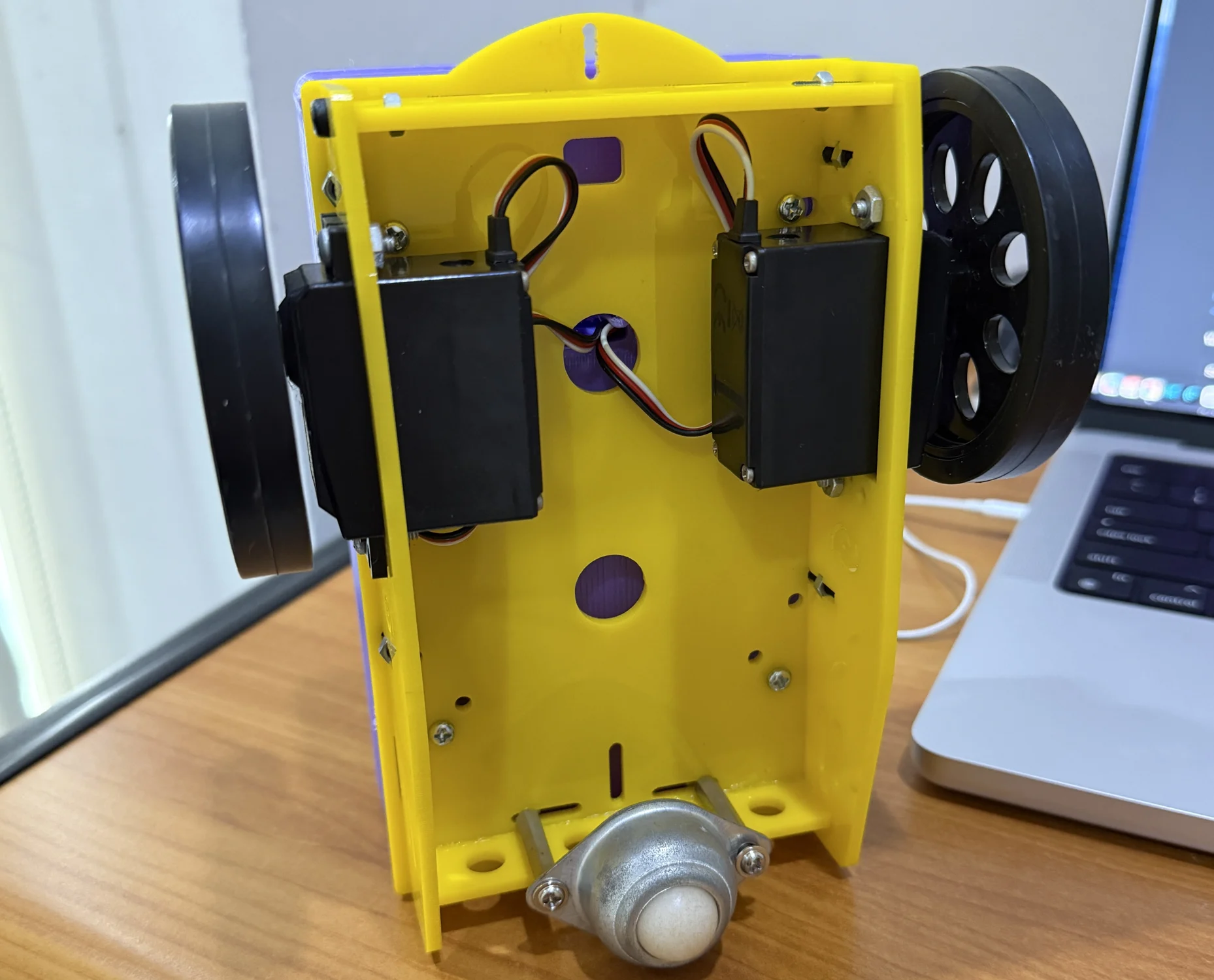
- Mount the two servos on opposite sides of the chassis, fit the wheels, and add a caster or skid.
- Secure the UNO Q above the chassis on standoffs. Fit the webcam pointing forward, with its cable clear of the wheels.
- Keep the battery low and secure. Leave access to the servo-power switch.
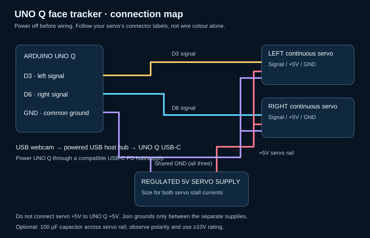
- Disconnect both power supplies, then make the connections below.
 + Enlarge wiring diagram
| Connection | Destination |
|---|---|
| Left servo signal | UNO Q digital D3 |
| Right servo signal | UNO Q digital D6 |
| Both servo positive leads | External regulated +5V servo rail |
| Both servo ground leads | External supply negative / ground |
| UNO Q GND | External servo-supply ground (common reference) |
| Webcam USB | USB-A data port on compatible powered host hub connected to UNO Q USB-C |
The optional capacitor goes across external servo +5V and ground, with its negative stripe to ground. It helps with brief noise; it cannot fix an undersized supply. Switch servo power off before changing wiring.
 + Click to enlarge
Let App Lab manage both halves
- Follow the official UNO Q setup guide to bring up the board, connect it to your network and open Arduino App Lab. Install supported board/App Lab updates before importing the application.
- Download and extract the source ZIP. Open the included project folder in App Lab using its import/open workflow. If your version requires creating a new app first, copy the project files into that app while preserving the folders.
- Keep
app.yaml,python/,sketch/, andassets/together. The web assets are essential; pasting only the sketch will not create a vision robot. - Leave servo power OFF. Connect the USB webcam through the hub and start the app. Allow initial downloads and compilation to finish; setup requires internet access even though inference runs locally.
Check the manifest
The application uses the video_object_detection brick with the face-detection model, plus the web_ui brick. The supplied manifest already selects these. The built-in model path does not require training a custom model.
name: Detect and follow robocar 2
description: Robot car that follows a target object.
bricks:
- arduino:video_object_detection:
    model: face-detection
- arduino:web_ui: {}
icon: 🚙
Read the wheel-control sketch
The MCU accepts wheel pulses from Python. D3 controls the left servo; D6 controls the right. The right-wheel inversion compensates for mirrored mounting. This is the complete upstream sketch, not a standalone replacement for the full app.
Show complete MCU sketch · sketch/sketch.ino
// SPDX-FileCopyrightText: Copyright (C) ARDUINO SRL (http://www.arduino.cc)
//
// SPDX-License-Identifier: MPL-2.0

// -----------------------------------------------------------------------
// MCU Sketch: Continuous-rotation servo control via Bridge RPC
//
// Two servos are driven via the Arduino Servo library on the UNO Q's
// STM32 MCU.  The MPU (Python) calls "set_wheel_pwm" over the Bridge
// and sends direct wheel pulse commands (microseconds).
// -----------------------------------------------------------------------

#include <Arduino_RouterBridge.h>
#include <Servo.h>

namespace {

// --- Pin assignments (change here if you re-wire) --------------------
const int kLeftServoPin  = 3;   // D3
const int kRightServoPin = 6;   // D6

// Standard continuous-rotation servo pulse range in microseconds.
const uint32_t kStopPulseUs = 1500;
const uint32_t kMinPulseUs  = 1000;
const uint32_t kMaxPulseUs  = 2000;

// Flip this if left wheel runs backward when commanded forward.
const bool kInvertLeftWheel  = false;
// Flip this if right wheel runs backward when commanded forward.
const bool kInvertRightWheel = true;

Servo leftServo;
Servo rightServo;

uint32_t clamp_pulse_us(int pulse_us) {
  if (pulse_us < static_cast<int>(kMinPulseUs)) return kMinPulseUs;
  if (pulse_us > static_cast<int>(kMaxPulseUs)) return kMaxPulseUs;
  return static_cast<uint32_t>(pulse_us);
}

uint32_t apply_invert(uint32_t pulse_us, bool invert) {
  if (!invert) return pulse_us;
  return (kStopPulseUs * 2U) - pulse_us;
}

}  // namespace

// --- Bridge RPC handler ----------------------------------------------
// Called from Python: Bridge.call("set_wheel_pwm", left_us, right_us)
bool set_wheel_pwm(int left_us, int right_us) {
  uint32_t left  = clamp_pulse_us(left_us);
  uint32_t right = clamp_pulse_us(right_us);

  left  = apply_invert(left,  kInvertLeftWheel);
  right = apply_invert(right, kInvertRightWheel);

  leftServo.writeMicroseconds(left);
  rightServo.writeMicroseconds(right);
  return true;
}

void setup() {
  Bridge.begin();

  leftServo.attach(kLeftServoPin);
  rightServo.attach(kRightServoPin);

  // Start both servos in the stopped position.
  leftServo.writeMicroseconds(kStopPulseUs);
  rightServo.writeMicroseconds(kStopPulseUs);

  // Expose the RPC so the MPU can control the servos.
  Bridge.provide_safe("set_wheel_pwm", set_wheel_pwm);
}

void loop() {
  // Nothing to do — servo state is updated via Bridge RPC callbacks.
}
Show Python controller · python/main.py
Use the downloadable project to retain all dependencies and web files.
# SPDX-FileCopyrightText: Copyright (C) ARDUINO SRL (http://www.arduino.cc)
#
# SPDX-License-Identifier: MPL-2.0

# -----------------------------------------------------------------------
# MPU Python App: Object detection -> wheel pulse controller
#
# Uses the VideoObjectDetection brick to detect objects on a USB camera.
# For TARGET_CLASS, the largest bounding box is used as the active target.
# The controller computes heading error from bbox center vs frame center
# and converts it into differential left/right wheel turn commands.
# -----------------------------------------------------------------------

from arduino.app_utils import App, Bridge
from arduino.app_bricks.web_ui import WebUI
from arduino.app_bricks.video_objectdetection import VideoObjectDetection
from datetime import datetime, UTC
import math
import threading
import time

# -----------------------------------------------------------------------
# Configuration — tweak these to change behaviour
# -----------------------------------------------------------------------

# Object class to track. Must match the model label exactly.
# Built-in face-detection model outputs "face".
TARGET_CLASS = "face"

# Minimum detection confidence (0.0-1.0).
DETECTION_CONFIDENCE = 0.5

# Seconds without any detection callback before the watchdog forces stop.
# At 3-4 FPS this must be comfortably above the frame interval (~300 ms).
NO_DETECTION_TIMEOUT = 1.5

# --- Follow controller tuning -------------------------------------------
# Servo pulse range for continuous-rotation wheels.
STOP_PULSE_US = 1500
MIN_PULSE_US = 1000
MAX_PULSE_US = 2000
PULSE_RANGE_US = 500

# Proportional gain: how aggressively turn speed scales with heading error.
# Higher = snappier but risks overshooting. Start low for desk testing.
STEER_GAIN = 0.15
# Hard cap on wheel speed used for turning [0-1]. 0.25 ≈ ±125 us from stop.
# Must exceed the servo dead zone (~±25-30 us for Parallax CR servos).
MAX_TURN_SPEED = 0.25
# Response curve exponent (1.0 = linear, <1.0 = compress large errors).
# Lower values make edge-of-frame speed closer to slight-off-center speed.
STEER_CURVE = 0.4
# Ignore heading errors smaller than this (suppresses jitter).
CENTER_DEADBAND = 0.05
# Seconds to coast on the last known target position before declaring lost.
TRACKING_TIMEOUT = 0.5

# --- Manual drive bias ----------------------------------------------------
# Fixed forward/backward bias independent of object size.
# Negative = backward, positive = forward, 0.0 = turn-only.
DRIVE_BIAS = 0.0
# Hard cap for manual drive bias [0-1]. 0.08 ≈ ±40 us from stop.
MAX_DRIVE_BIAS = 0.08

# Fallback frame dimensions when detector payload does not include frame size.
# Adjust to match your camera resolution (common: 320, 480, 640, 1280).
FRAME_WIDTH_FALLBACK = 640.0
FRAME_HEIGHT_FALLBACK = 480.0

# If left/right tracking is mirrored, set STEER_SIGN to -1.0.
STEER_SIGN = 1.0

# Match MCU wheel inversion so debug status reflects physical motion.
LEFT_WHEEL_INVERTED = False
RIGHT_WHEEL_INVERTED = True

# Lost-target behavior: default stop, optionally rotate slowly to search.
SEARCH_WHEN_LOST = False
SEARCH_SPEED = 0.2

# -----------------------------------------------------------------------
# Bricks initialisation
# -----------------------------------------------------------------------

ui = WebUI()
detection_stream = VideoObjectDetection(
    confidence=DETECTION_CONFIDENCE, debounce_sec=0.0
)

# Let the web UI adjust the confidence threshold live via a slider.
ui.on_message(
    "override_th",
    lambda sid, threshold: detection_stream.override_threshold(threshold),
)


def _set_steer_gain(sid, value):
    global STEER_GAIN
    STEER_GAIN = _clamp(_safe_float(value, STEER_GAIN), 0.0, 0.30)
    print(f"steer_gain overridden to {STEER_GAIN:.3f}")


ui.on_message("override_steer_gain", _set_steer_gain)


def _set_drive_bias(sid, value):
    global DRIVE_BIAS
    DRIVE_BIAS = _clamp(_safe_float(value, DRIVE_BIAS), -MAX_DRIVE_BIAS, MAX_DRIVE_BIAS)
    print(f"drive_bias overridden to {DRIVE_BIAS:.3f}")


ui.on_message("override_drive_bias", _set_drive_bias)

_emergency_stopped = False


def _emergency_stop(sid, value=None):
    global _emergency_stopped
    _emergency_stopped = True
    _send_wheel_cmd(STOP_PULSE_US, STOP_PULSE_US, "emergency_stop", urgent=True)
    print("EMERGENCY STOP activated")


def _emergency_release(sid, value=None):
    global _emergency_stopped
    _emergency_stopped = False
    print("Emergency stop released")


ui.on_message("emergency_stop", _emergency_stop)
ui.on_message("emergency_release", _emergency_release)


def _motor_test(sid, value=None):
    """Run a left-right-stop test sequence to verify servo wiring.

    Uses large pulse offsets (1300/1700) and sends directly via Bridge.notify
    to bypass all control logic and rate limiting — pure hardware test.
    """
    global _emergency_stopped
    _emergency_stopped = True  # Pause tracking during test.
    print("MOTOR TEST: starting")

    steps = [
        ("left",  1300, 1700, 1.5),
        ("stop",  1500, 1500, 0.5),
        ("right", 1700, 1300, 1.5),
        ("stop",  1500, 1500, 0.0),
    ]
    for label, left, right, pause in steps:
        print(f"MOTOR TEST: {label} L={left} R={right}")
        Bridge.notify("set_wheel_pwm", left, right)
        if pause > 0:
            time.sleep(pause)

    _emergency_stopped = False
    ui.send_message("motor_test_done", message={})
    print("MOTOR TEST: done")


ui.on_message("motor_test", _motor_test)

# -----------------------------------------------------------------------
# Wheel command tracking
# -----------------------------------------------------------------------

_last_wheel = {"left": STOP_PULSE_US, "right": STOP_PULSE_US}
_last_detection_ts = 0.0
_watchdog_started = False
_logged_sample = False
_last_state_publish_ts = 0.0
_last_bridge_ts = 0.0
# Minimum interval between Bridge.notify() calls.
# The UNO Q Bridge has no queue — spamming notify() crashes the serial link.
MIN_BRIDGE_INTERVAL = 0.05  # 50 ms → max 20 cmd/s

# Cached target for coasting when detection is momentarily lost.
_last_target = None
_last_target_ts = 0.0


# -----------------------------------------------------------------------
# Bounding-box helpers
# -----------------------------------------------------------------------

def _bbox_from_entry(entry):
    """Extract (xmin, ymin, xmax, ymax) from a detection dict, or None.

    The VideoObjectDetection brick produces:
        {"confidence": float, "bounding_box_xyxy": (xmin, ymin, xmax, ymax)}
    """
    if not isinstance(entry, dict):
        return None
    bb = entry.get("bounding_box_xyxy")
    if isinstance(bb, (list, tuple)) and len(bb) >= 4:
        return bb[0], bb[1], bb[2], bb[3]
    return None


def _box_center_x(entry):
    """Return the horizontal centre of a detection's bounding box (pixels)."""
    bb = _bbox_from_entry(entry)
    if bb is None:
        return None
    return (bb[0] + bb[2]) / 2


def _box_area(entry):
    """Return bbox area in pixels."""
    bb = _bbox_from_entry(entry)
    if bb is None:
        return None
    w = max(0.0, bb[2] - bb[0])
    h = max(0.0, bb[3] - bb[1])
    return w * h


# -----------------------------------------------------------------------
# Detection → left/right decision
# -----------------------------------------------------------------------

def _collect_target_boxes(detections):
    """Return boxes for TARGET_CLASS from the brick payload.

    The VideoObjectDetection brick wraps detections in a list per label:
        {label: [{"confidence": float, "bounding_box_xyxy": (x0,y0,x1,y1)}, ...]}
    """
    boxes = []
    if not isinstance(detections, dict):
        return boxes

    entry = detections.get(TARGET_CLASS)
    if isinstance(entry, list):
        for det in entry:
            if isinstance(det, dict) and "bounding_box_xyxy" in det:
                boxes.append(det)
    elif isinstance(entry, dict) and "bounding_box_xyxy" in entry:
        boxes.append(entry)

    return boxes


def _clamp(value, low, high):
    return max(low, min(high, value))


def _safe_float(value, fallback):
    try:
        return float(value)
    except (TypeError, ValueError):
        return fallback


def _speed_to_pulse(speed):
    speed = _clamp(speed, -1.0, 1.0)
    pulse = STOP_PULSE_US + int(speed * PULSE_RANGE_US)
    return _clamp(pulse, MIN_PULSE_US, MAX_PULSE_US)


def _pulse_to_speed(pulse):
    return _clamp((pulse - STOP_PULSE_US) / PULSE_RANGE_US, -1.0, 1.0)


def _movement_status(left_us, right_us, mode):
    left_speed = _pulse_to_speed(left_us)
    right_speed = _pulse_to_speed(right_us)
    forward = (left_speed + right_speed) * 0.5
    turn = (left_speed - right_speed) * 0.5

    if abs(left_speed) < 0.05 and abs(right_speed) < 0.05:
        status = "stopped"
    elif abs(turn) > abs(forward) + 0.05:
        status = "turning right" if turn > 0 else "turning left"
    elif forward > 0:
        status = "going forward"
    else:
        status = "going backward"

    if mode == "search":
        status = f"searching ({status})"
    elif mode == "lost_stop":
        status = "lost target - stopped"

    return status, round(forward, 2), round(turn, 2)


def _best_target(boxes):
    """Return (center_x_norm, area_frac) for the largest valid target, or None."""
    best_cx = None
    best_area = -1.0
    best_bbox = None
    for box in boxes:
        cx = _box_center_x(box)
        if cx is None:
            continue

        area = _box_area(box) or 0.0

        # bbox coordinates are in pixels; normalise cx to 0-1.
        center_x_norm = cx / FRAME_WIDTH_FALLBACK

        if area > best_area:
            best_area = area
            best_cx = center_x_norm
            best_bbox = _bbox_from_entry(box)

    if best_cx is None:
        return None

    frame_area = FRAME_WIDTH_FALLBACK * FRAME_HEIGHT_FALLBACK
    area_frac = best_area / frame_area if frame_area > 0 else 0.0

    return best_cx, area_frac, best_bbox


def _compute_wheel_command(detections: dict):
    """Map detections to wheel command tuple, or None when target not found."""
    global _last_target, _last_target_ts

    boxes = _collect_target_boxes(detections)
    result = _best_target(boxes)

    if result is not None:
        target_cx, area_frac, bbox = result
        _last_target = (target_cx, area_frac, bbox)
        _last_target_ts = time.monotonic()
        mode = "tracking"
    elif _last_target is not None and (time.monotonic() - _last_target_ts) < TRACKING_TIMEOUT:
        target_cx, area_frac, bbox = _last_target
        mode = "coasting"
    else:
        _last_target = None
        return None

    # --- Steering (left/right) ---
    heading_error = (target_cx - 0.5) * 2.0
    if abs(heading_error) < CENTER_DEADBAND:
        heading_error = 0.0

    shaped = math.copysign(abs(heading_error) ** STEER_CURVE, heading_error)
    turn = _clamp(STEER_SIGN * STEER_GAIN * shaped, -MAX_TURN_SPEED, MAX_TURN_SPEED)

    # --- Manual drive bias (forward/backward) ---
    forward = DRIVE_BIAS

    # Turn pulses first, then layer forward/backward as an equal pulse shift
    # on both wheels.  This works correctly with MCU-side inversion: adding
    # +N us to both wheels here becomes +N on left and -N (physical) on right
    # after the MCU mirrors the right pulse around 1500 us → net forward.
    left_us = _speed_to_pulse(turn)
    right_us = _speed_to_pulse(-turn)
    fwd_offset = int(forward * PULSE_RANGE_US)
    left_us = _clamp(left_us + fwd_offset, MIN_PULSE_US, MAX_PULSE_US)
    right_us = _clamp(right_us + fwd_offset, MIN_PULSE_US, MAX_PULSE_US)
    print(f"controller cx={target_cx:.3f} heading={heading_error:.3f} turn={turn:.3f} area={area_frac:.3f} fwd={forward:.3f} mode={mode}")
    return left_us, right_us, mode, area_frac


def _lost_target_command():
    if not SEARCH_WHEN_LOST:
        return STOP_PULSE_US, STOP_PULSE_US, "lost_stop", None
    rotate = _clamp(SEARCH_SPEED, 0.0, 1.0)
    left_us = _speed_to_pulse(rotate)
    right_us = _speed_to_pulse(-rotate)
    return left_us, right_us, "search", None


# -----------------------------------------------------------------------
# Bridge communication
# -----------------------------------------------------------------------

def _send_wheel_cmd(left_us: int, right_us: int, mode: str, area_frac=None,
                    urgent: bool = False):
    """Send wheel pulse command and publish debug state to the UI.

    Set urgent=True for safety-critical commands (e.g. emergency stop) to
    bypass rate limiting and the same-command cache.
    """
    global _last_state_publish_ts, _last_bridge_ts
    same_cmd = left_us == _last_wheel["left"] and right_us == _last_wheel["right"]
    status, forward, turn = _movement_status(left_us, right_us, mode)
    now = time.monotonic()

    if urgent or (not same_cmd) or (now - _last_state_publish_ts > 0.5):
        print(
            f"wheel_cmd left_us={left_us} right_us={right_us} "
            f"status='{status}' mode={mode} fwd={forward} turn={turn}"
        )
        msg = {
            "status": status,
            "mode": mode,
            "left_us": left_us,
            "right_us": right_us,
            "forward": forward,
            "turn": turn,
            "left_speed": round(_pulse_to_speed(left_us), 2),
            "right_speed": round(_pulse_to_speed(right_us), 2),
            "timestamp": datetime.now(UTC).isoformat(),
        }
        if area_frac is not None:
            msg["area_frac"] = round(area_frac, 4)
        ui.send_message("robot_state", message=msg)
        _last_state_publish_ts = now

    if same_cmd and not urgent:
        return

    # Rate-limit Bridge calls to avoid crashing the serial link.
    if not urgent and now - _last_bridge_ts < MIN_BRIDGE_INTERVAL:
        return

    _last_wheel["left"] = left_us
    _last_wheel["right"] = right_us
    _last_bridge_ts = now
    Bridge.notify("set_wheel_pwm", left_us, right_us)


# -----------------------------------------------------------------------
# Watchdog — stop servos when detections dry up
# -----------------------------------------------------------------------

def _watchdog_loop():
    """Background thread: fallback command if detection callbacks stop."""
    while True:
        time.sleep(0.25)
        if _emergency_stopped:
            continue
        if time.monotonic() - _last_detection_ts > NO_DETECTION_TIMEOUT:
            _send_wheel_cmd(*_lost_target_command())


# -----------------------------------------------------------------------
# Main detection callback
# -----------------------------------------------------------------------

def on_detections(detections):
    """Called by the VideoObjectDetection brick whenever objects are found."""
    global _logged_sample, _last_detection_ts, _watchdog_started

    # Log one sample so you can inspect the payload format.
    if not _logged_sample:
        print(f"sample_detections {detections}")
        _logged_sample = True
        if not _watchdog_started:
            _watchdog_started = True
            threading.Thread(target=_watchdog_loop, daemon=True).start()

    _last_detection_ts = time.monotonic()

    if _emergency_stopped:
        return

    # Forward every detection to the web UI.
    # The brick wraps detections as {label: [det, ...]} (list per label).
    if isinstance(detections, dict):
        for key, value in detections.items():
            dets = value if isinstance(value, list) else [value]
            for det in dets:
                if not isinstance(det, dict):
                    continue
                entry = {
                    "content": key,
                    "confidence": det.get("confidence"),
                    "timestamp": datetime.now(UTC).isoformat(),
                }
                bb = det.get("bounding_box_xyxy")
                if bb is not None:
                    entry["bbox"] = list(bb)
                ui.send_message("detection", message=entry)

    # Compute and send wheel command; fallback if target class is missing.
    cmd = _compute_wheel_command(detections)
    if cmd is None:
        cmd = _lost_target_command()
    _send_wheel_cmd(*cmd)


detection_stream.on_detect_all(on_detections)

App.run()
The project pins library versions in sketch/sketch.yaml. If dependency resolution fails on a newer App Lab release, save the full build error and check the upstream project and Arduino release notes before changing versions. Hardware compilation has not been verified here.
Camera first. Wheels second.
A. Confirm detection with motor power off
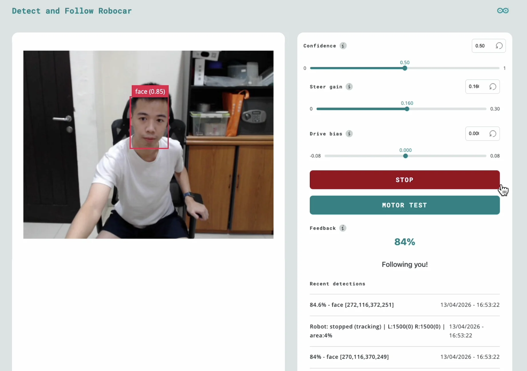
Use App Lab’s displayed web-app link. The creator documents the dashboard at http://<UNO_Q_IP>:7000. Open it from a computer on the same network; UNO_Q_IP means the board’s local address, not your computer’s address. Confirm the live camera feed and detection log change when your face enters the frame.
B. Raise the wheels before the motor test
Place the chassis on a secure support with both wheels off the surface. Keep fingers and cables clear. Check wiring again, switch servo power on, and run the dashboard’s Motor Test. The source test briefly uses 1300/1700 µs pulses, which can spin the wheels briskly. Switch motor power off if anything behaves unexpectedly.
C. Test tracking at floor level
With drive bias at zero, put the robot on a clear, level floor. Move one face slowly from the centre to either side of the camera view. The robot should turn to bring the face back toward centre. Cover the camera briefly and check that it stops after the configured lost-target timeout.
This build has no cliff or obstacle sensors. Do not run it near a table edge. The dashboard stop relies on a working connection; the physical servo-power switch is your dependable way to cut motor power. The stock MCU sketch has no independent timeout if Python or the Bridge link fails.
 + Click to enlarge
Small changes beat wild guesses
| Setting in python/main.py | Starting value | Effect |
|---|---|---|
STEER_GAIN | 0.15 | Higher values turn more strongly. Lower it if the robot swings left and right. |
CENTER_DEADBAND | 0.05 | A larger centre zone reduces small corrective twitches. |
STEER_SIGN | 1.0 | Try −1.0 if it consistently turns away from the target. |
DRIVE_BIAS | 0.0 | Leave at zero for turn-only operation. |
TRACKING_TIMEOUT | 0.5 seconds | How long the controller holds the last target after losing the face. |
SEARCH_WHEN_LOST | False | Leave disabled so losing the target stops motion. |
Change one setting, test it, and record the result. Live dashboard slider adjustments need to be copied into the Python defaults if you want them after a restart. If a servo creeps at the nominal 1500 µs stop pulse, use its documented neutral adjustment procedure or calibrate its neutral value before running tracking.
Why the steering works
The controller compares the face’s horizontal centre with the image centre. A face near the middle produces little steering; one farther to a side produces more. Differential wheel commands turn the chassis. The program chooses the largest detected face, so test with one person first.
Results depend on lighting, camera view, model confidence and processing load. The source’s documentation gives differing frame-rate descriptions; we make no fixed performance promise.
Find the fault without rebuilding everything
| Symptom | Check this first |
|---|---|
| No dashboard | Confirm the app is running, use its displayed address, check the local network and firewall. Guest Wi-Fi can block devices from reaching each other. |
| Dashboard loads, camera does not | Check that the hub supports USB data/host operation and power delivery. Reseat the camera, inspect app logs, and try a known UVC camera. |
| Face appears but no detection | Improve lighting, face the camera, inspect sample_detections, and confirm the model label is exactly face. |
| Detection works, no wheel motion | Use the raised-wheel motor test. Verify external servo power, common ground, D3/D6 and continuous-rotation servo type. |
| Board resets when wheels start | Check supply capacity, hub stability, connectors and power isolation. A capacitor alone will not solve sustained voltage drop. |
| It turns the wrong way | Check mirrored wheel mounting and inversion; then change steering sign if detection coordinates are mirrored. |
| It jitters or overshoots | Reduce steering gain, increase deadband a little, and remove mechanical cable drag. |
| Robot keeps moving after a fault | Cut external servo power. The upstream Python watchdog cannot protect against every process or communication failure. |
Next upgrade: an MCU timeout
A worthwhile follow-up is an independent MCU watchdog that stops the wheels unless fresh commands arrive. Add and test it before experimenting with forward motion. Obstacle sensing and a physical stop control are further upgrades; they are not included in this starter application.
Study links & project credit
Original code, documentation and licensing
- Samuel Alexander: original project, photos, code and STL files
- Original Arduino Project Hub build · published May 21, 2026
- Arduino UNO Q hardware, pinout and setup
- Arduino App Lab documentation
The downloadable ZIP is an unmodified upstream snapshot at commit 6c3b286b75d503c536e54b3cbaadad9c5f4c9bca. The repository includes an Apache-2.0 root license; individual application files retain their MPL-2.0 headers and other included notices. Those notices remain in the archive. Project photography is reproduced from that repository with attribution. WolfieWeb’s wiring schematic and tutorial text are new.
Guide prepared October 27, 2026. Verified against the downloaded source; no physical build test is claimed.