
Arduino Tutorials for Beginners
Learn Arduino by actually building something. On this page, you’ll go step-by-step through real projects—LEDs, sensors, motors, and displays—so you can go from zero to working builds fast.
Step 4 of 5: Arduino Projects
Printable Pinout PDF Lab Manuals
Each Arduino tutorial now has its own printable wiring guide with pin codes, step-by-step instructions, expected results, and troubleshooting. Use these at the workbench while you build.
What you’ll learn on this page
If you’re just getting started with Arduino, the biggest problem usually is not lack of information. It’s not knowing where to begin. That’s what this page fixes. You’ll build real projects in the right order, understand what each part does, and see results as you go.
- Learn what each component does before you wire it
- Understand what the code is doing instead of pasting blindly
- Build confidence with fast beginner wins before harder projects
- Use the PDF as a printable bench guide while you build
- Turn simple experiments into real robotics foundations
Inside this rebuild
Everything you need for these builds
Before you start, make sure you have the parts you need. The easiest move is to grab the full Arduino starter kit because it includes almost everything used in these builds, so you do not get stuck halfway through.
Best main seller: full Arduino starter kit
Most beginners do better with one complete kit than buying parts one by one. It is the easiest way to start building without missing something important.
Affiliate note: some links on this page are affiliate links. If someone buys through them, WolfieWeb may earn a commission at no extra cost to the buyer.
Arduino LED Blink Tutorial
This is your first real Arduino build. You’ll learn how to control an output, wire a simple circuit, and upload your first working code. Once this works, everything else gets easier.
Most beginners start with the full kit so they do not get stuck missing wires, a breadboard, or basic parts halfway through the build.
- Step 1: Place the LED on the breadboard and add a 220Ω resistor in series.
- Step 2: Connect the LED positive leg to a digital output pin, usually pin 13 or pin 8.
- Step 3: Connect the LED negative side through the resistor to GND.
- Step 4: Upload the blink sketch and confirm the board and COM port are correct in the IDE.
- Step 5: Change the delay values to see how timing changes the visible blink pattern.
void setup() {
  pinMode(13, OUTPUT);
}

void loop() {
  digitalWrite(13, HIGH);
  delay(500);
  digitalWrite(13, LOW);
  delay(500);
}
Video not loading? Watch on YouTube.
Arduino Ultrasonic Sensor Tutorial
Now you’re adding awareness to your build. This sensor lets your Arduino measure distance, which is the foundation for obstacle avoidance, robotics, and automation projects.
The full kit is still the easiest way to start, but this exact HC-SR04 link is here if you only need the distance sensor.
- Step 1: Wire VCC to 5V and GND to GND.
- Step 2: Connect TRIG to one digital pin and ECHO to another.
- Step 3: Send a short trigger pulse from the Arduino.
- Step 4: Measure how long the echo pin stays high.
- Step 5: Convert that time into distance and print it to the serial monitor.
const int trigPin = 9;
const int echoPin = 10;

void setup() {
  pinMode(trigPin, OUTPUT);
  pinMode(echoPin, INPUT);
  Serial.begin(9600);
}

void loop() {
  digitalWrite(trigPin, LOW);
  delayMicroseconds(2);
  digitalWrite(trigPin, HIGH);
  delayMicroseconds(10);
  digitalWrite(trigPin, LOW);

  long duration = pulseIn(echoPin, HIGH);
  float distanceCm = duration * 0.0343 / 2;
  Serial.println(distanceCm);
  delay(250);
}
Video not loading? Watch on YouTube.
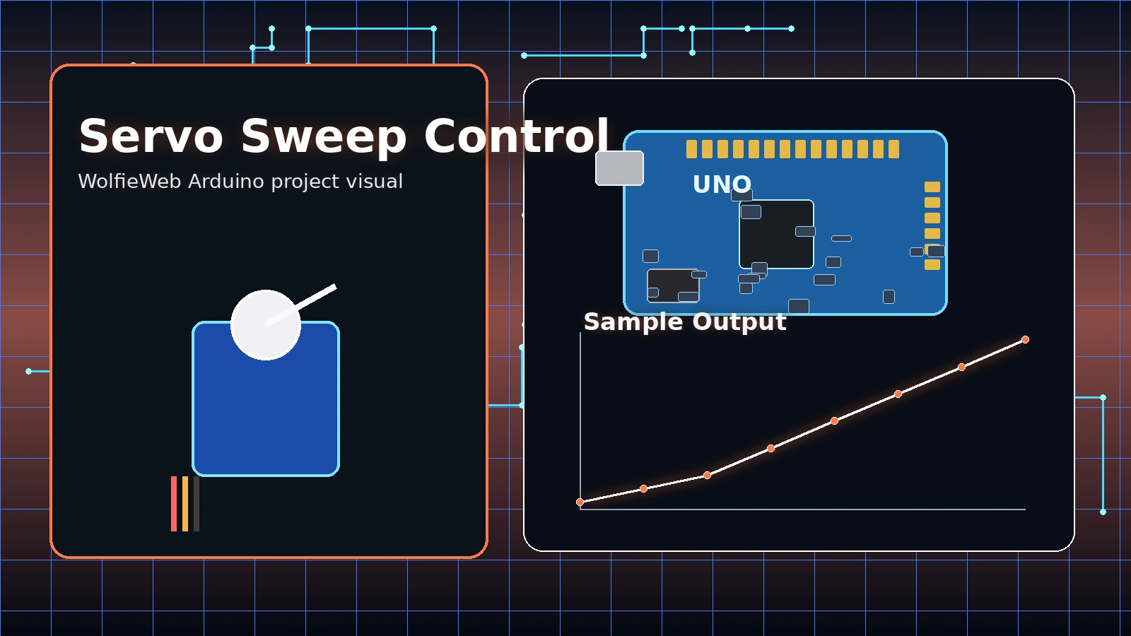
Arduino Servo Motor Tutorial
This is where things start moving. You’ll control a servo motor with code, which is the first step toward building robotic arms, moving parts, and real machines.
Motion sells. Keep the full kit as the main click, then offer the exact SG90 servo pack for readers upgrading old kits.
- Step 1: Connect servo power to 5V and ground to GND.
- Step 2: Connect the signal wire to a PWM-capable control pin.
- Step 3: Use the Servo library so you are not manually generating control pulses.
- Step 4: Sweep the servo between angles to confirm clean movement.
- Step 5: Listen for buzzing or jitter. That usually means weak power or bad wiring.
#include <Servo.h>

Servo myServo;

void setup() {
  myServo.attach(9);
}

void loop() {
  myServo.write(0);
  delay(700);
  myServo.write(90);
  delay(700);
  myServo.write(180);
  delay(700);
}
Video not loading? Watch on YouTube.
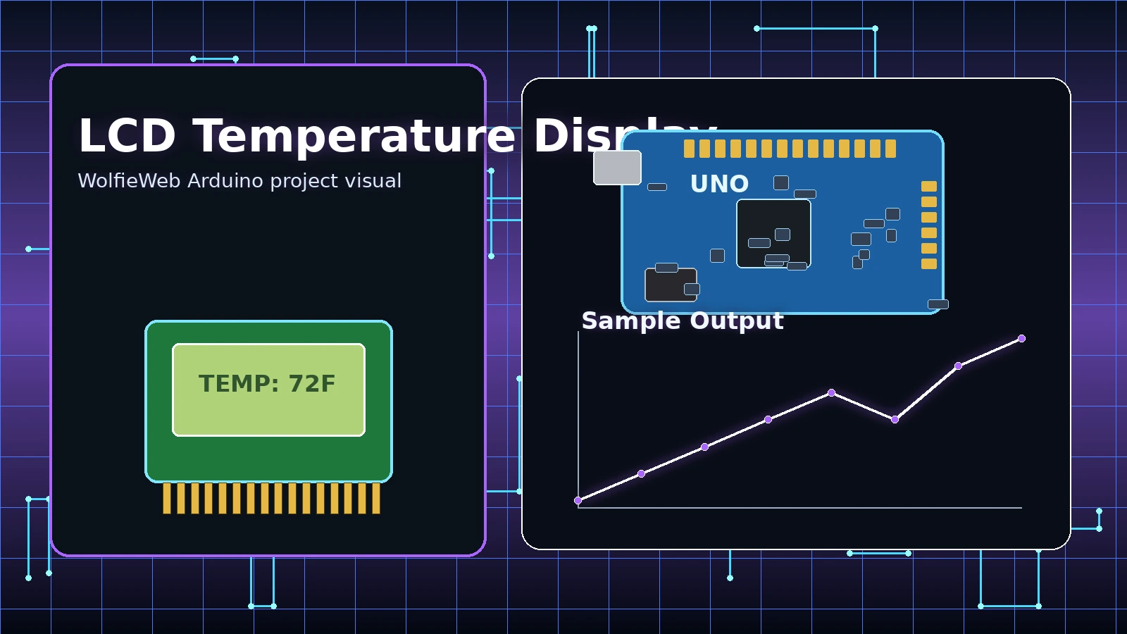
Arduino LCD Display Tutorial
Instead of guessing what your project is doing, you’ll display it. This lets you show real-time data on a screen, which makes your build feel complete and easier to understand.
The full kit is still the safest first buy, but the exact LCD module link is here if you only need the display piece.
- Step 1: Wire the LCD carefully. One wrong connection can make it look dead.
- Step 2: Add the proper LCD library and set the correct pin layout.
- Step 3: Read a temperature or sensor value from the Arduino.
- Step 4: Print a label and the live reading to the LCD.
- Step 5: Adjust contrast if the text is faint or invisible.
#include <LiquidCrystal.h>

LiquidCrystal lcd(12, 11, 5, 4, 3, 2);

void setup() {
  lcd.begin(16, 2);
  lcd.print("Temp Monitor");
}

void loop() {
  int sensorValue = analogRead(A0);
  lcd.setCursor(0, 1);
  lcd.print("Value: ");
  lcd.print(sensorValue);
  lcd.print("   ");
  delay(500);
}
Video not loading? Watch on YouTube.
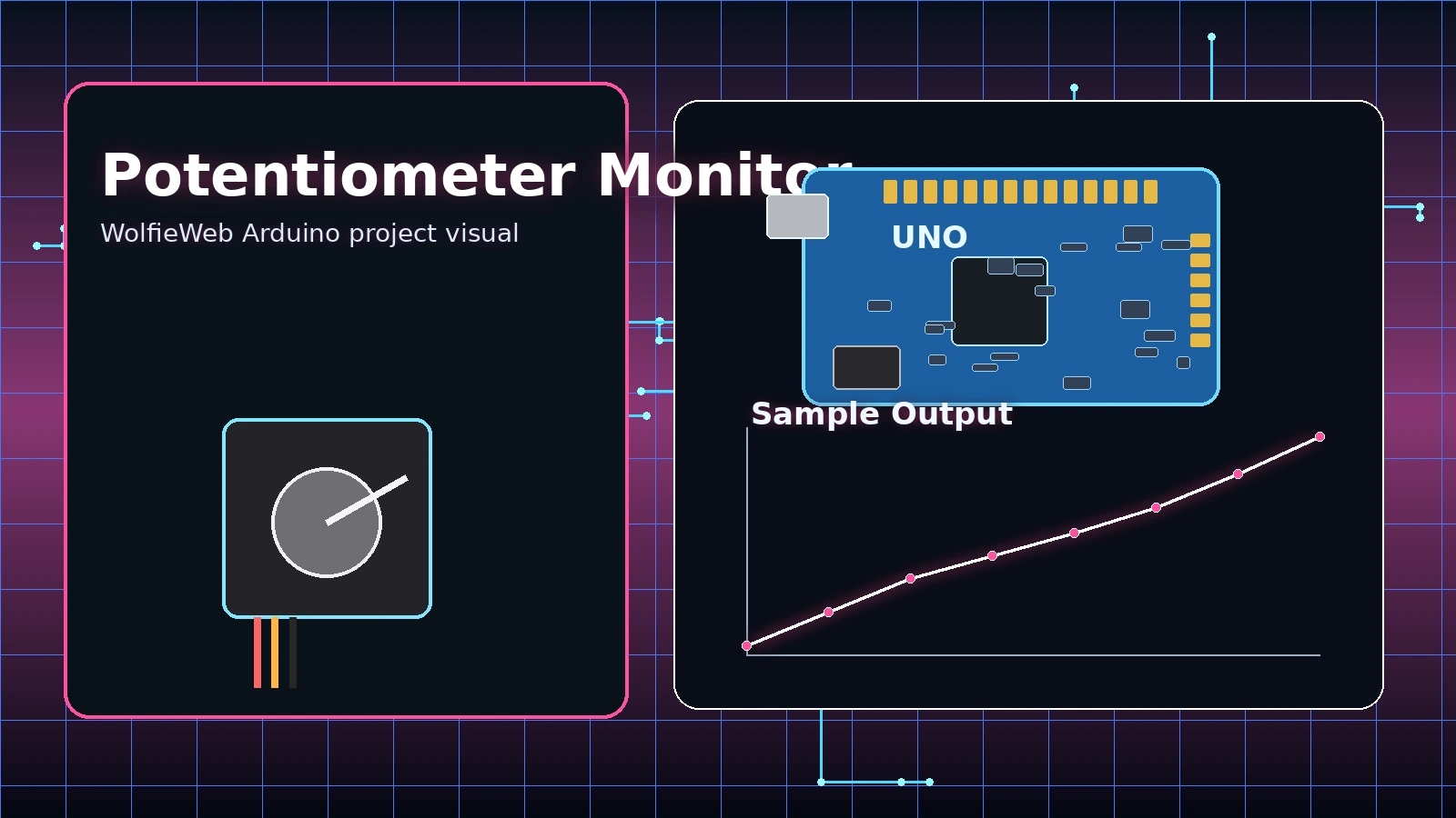
Arduino Potentiometer Tutorial
This teaches you how to read real-world input. Turn the knob and watch your Arduino respond instantly. This is how you control speed, brightness, and behavior in your projects.
Analog input is simple, but most readers still need jumper wires and a breadboard. That is why the full kit should stay on top.
- Step 1: Wire one side of the potentiometer to 5V and the other to GND.
- Step 2: Connect the center pin to analog input A0.
- Step 3: Read the value in the sketch using analogRead.
- Step 4: Print the result to the serial monitor so you can see the range move.
- Step 5: Map the value later to LED brightness, servo angle, or motor speed.
void setup() {
  Serial.begin(9600);
}

void loop() {
  int knobValue = analogRead(A0);
  Serial.println(knobValue);
  delay(200);
}
Video not loading? Watch on YouTube.
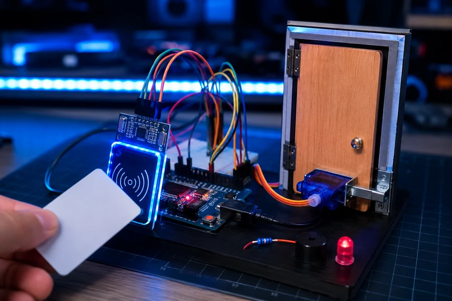
Arduino RFID Smart Lock Tutorial
This intermediate build turns your Arduino into a simple access-control system. You scan an RFID card, the Arduino checks whether the card is approved, and a servo moves a latch to simulate locking or unlocking a small door. This is a big step up from beginner wiring because you are combining input, logic, feedback, and motion into one complete project.
MyStore parts code: every ordering link on this tutorial uses the WolfieWeb Amazon tag wolfieweb88-20, so the parts section is ready for your store/affiliate setup.
Parts you need
- Arduino Uno: the main controller that reads the RFID module and commands the servo.
- MFRC522 RFID module: reads the card or key fob ID.
- RFID card or key fob: the “key” used to unlock the project.
- SG90 micro servo: moves the lock latch when access is approved.
- Green and red LEDs: green means approved, red means denied.
- Piezo buzzer: gives an audio beep for scan feedback.
- Jumper wires and breadboard: keeps the build clean and easy to change.
RFID module wiring
- VCC: connect to 3.3V. Do not use 5V on the MFRC522 module unless your specific board says it is 5V tolerant.
- GND: connect to Arduino GND.
- RST: connect to digital pin 9.
- SDA / SS: connect to digital pin 10.
- MOSI: connect to digital pin 11.
- MISO: connect to digital pin 12.
- SCK: connect to digital pin 13.
Servo, LED, and buzzer wiring
- Servo signal: connect the orange/yellow servo wire to digital pin 6.
- Servo power: connect the red servo wire to 5V.
- Servo ground: connect the brown/black servo wire to GND.
- Green LED: connect the long leg through a 220Ω resistor to pin 4, short leg to GND.
- Red LED: connect the long leg through a 220Ω resistor to pin 5, short leg to GND.
- Buzzer: connect the positive side to pin 3 and the negative side to GND.
Build steps
- Step 1: Wire only the RFID module first. Do not add the servo yet. Upload a simple card-read test and confirm the serial monitor shows a card UID.
- Step 2: Scan your RFID card and copy the UID from the serial monitor. This UID becomes your approved key.
- Step 3: Add the servo and test that it moves from locked position to unlocked position. A good starting test is 0 degrees for locked and 90 degrees for unlocked.
- Step 4: Add the green LED, red LED, and buzzer so the project gives visible and audible feedback.
- Step 5: Add the access-control logic. If the scanned UID matches your approved UID, unlock the servo. If not, flash red and deny access.
- Step 6: Mount the servo beside a small cardboard, foam board, or wooden door latch. Keep it simple. The first goal is reliable movement, not a perfect security door.
- Step 7: Test at least ten scans in a row. A good project should approve the correct card every time and reject the wrong card every time.
#include <SPI.h>
#include <MFRC522.h>
#include <Servo.h>

#define SS_PIN 10
#define RST_PIN 9

MFRC522 rfid(SS_PIN, RST_PIN);
Servo lockServo;

const int servoPin = 6;
const int buzzerPin = 3;
const int greenLed = 4;
const int redLed = 5;

// Replace this with your own card UID from the Serial Monitor.
String approvedUID = "DE AD BE EF";

void setup() {
  Serial.begin(9600);
  SPI.begin();
  rfid.PCD_Init();

  lockServo.attach(servoPin);
  lockServo.write(0); // locked position

  pinMode(buzzerPin, OUTPUT);
  pinMode(greenLed, OUTPUT);
  pinMode(redLed, OUTPUT);

  Serial.println("RFID Smart Lock Ready");
}

void loop() {
  if (!rfid.PICC_IsNewCardPresent()) return;
  if (!rfid.PICC_ReadCardSerial()) return;

  String cardUID = "";
  for (byte i = 0; i < rfid.uid.size; i++) {
    if (rfid.uid.uidByte[i] < 0x10) cardUID += "0";
    cardUID += String(rfid.uid.uidByte[i], HEX);
    if (i < rfid.uid.size - 1) cardUID += " ";
  }
  cardUID.toUpperCase();

  Serial.print("Scanned UID: ");
  Serial.println(cardUID);

  if (cardUID == approvedUID) {
    unlockDoor();
  } else {
    denyAccess();
  }

  rfid.PICC_HaltA();
  rfid.PCD_StopCrypto1();
}

void unlockDoor() {
  digitalWrite(greenLed, HIGH);
  tone(buzzerPin, 1200, 150);
  lockServo.write(90);
  delay(3000);
  lockServo.write(0);
  digitalWrite(greenLed, LOW);
}

void denyAccess() {
  digitalWrite(redLed, HIGH);
  tone(buzzerPin, 300, 400);
  delay(700);
  digitalWrite(redLed, LOW);
}
Troubleshooting
- No card detected: check 3.3V power, GND, SDA pin 10, and SPI pins 11, 12, and 13.
- Servo twitches or resets the board: the servo may be pulling too much current. Use a separate 5V servo supply and connect the grounds together.
- Correct card is denied: your UID string does not match exactly. Copy it from the serial monitor and keep the spacing the same.
- RFID works until servo moves: power noise is likely. Keep servo wires away from the RFID antenna and use a stronger power source.
Video not loading? Watch on YouTube or search for Arduino RFID lock servo MFRC522 tutorial.
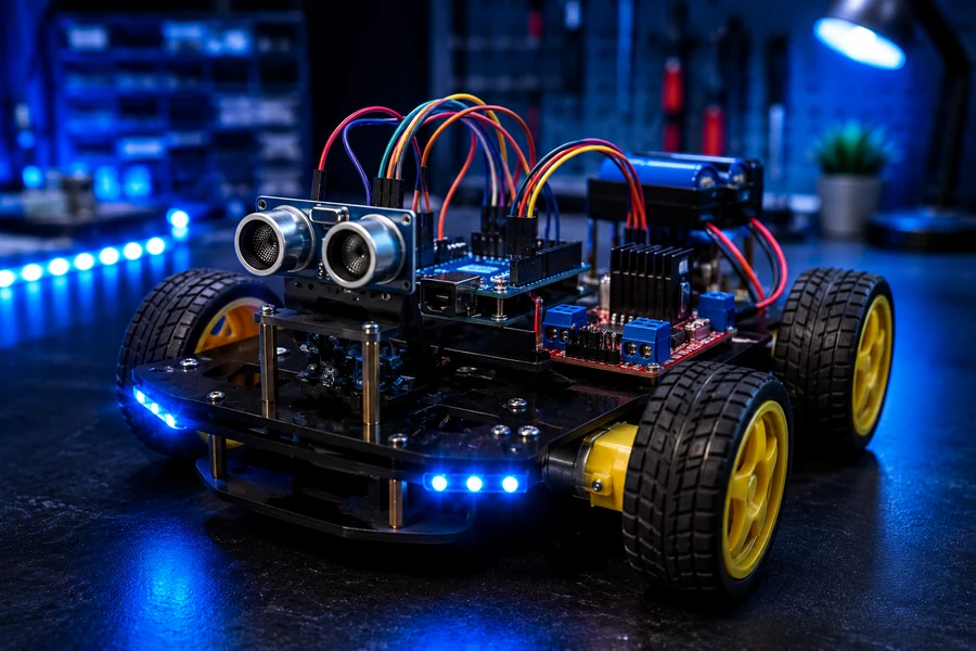
Arduino Obstacle Avoiding Robot Car Tutorial
This is the build where your Arduino starts acting like a real robot. The ultrasonic sensor measures distance, the Arduino decides whether the path is safe, and the motor driver controls the wheels. This project combines sensors, motors, power, and decision-making into one moving machine.
MyStore parts code: these ordering buttons use wolfieweb88-20 in the links, matching the rest of your WolfieWeb parts system.
Parts you need
- Arduino Uno: the robot brain.
- 2WD robot chassis: frame, wheels, DC motors, and caster wheel.
- L298N motor driver: lets the Arduino control motor direction and speed.
- HC-SR04 ultrasonic sensor: measures distance in front of the robot.
- Battery pack: powers the motors. Do not rely only on USB power for a moving robot.
- Jumper wires: connect the Arduino, motor driver, and sensor.
- Optional switch: makes the robot easier and safer to turn on and off.
Motor driver wiring
- Left motor: connect the two left motor wires to OUT1 and OUT2 on the L298N.
- Right motor: connect the two right motor wires to OUT3 and OUT4 on the L298N.
- ENA: connect to Arduino pin 5 for left motor speed control.
- IN1: connect to Arduino pin 7.
- IN2: connect to Arduino pin 8.
- IN3: connect to Arduino pin 11.
- IN4: connect to Arduino pin 12.
- ENB: connect to Arduino pin 6 for right motor speed control.
- Motor battery positive: connect to L298N 12V/VIN motor power input.
- Battery negative: connect to L298N GND and Arduino GND. Shared ground is not optional.
Ultrasonic sensor wiring
- VCC: connect to Arduino 5V.
- GND: connect to Arduino GND.
- TRIG: connect to Arduino pin 9.
- ECHO: connect to Arduino pin 10.
Build steps
- Step 1: Assemble the chassis first. Mount both DC motors firmly, attach the wheels, and make sure nothing rubs against the frame.
- Step 2: Mount the Arduino and L298N on the chassis. Keep the motor driver near the motors so the motor wires stay short.
- Step 3: Wire the motors to the L298N. Lift the robot off the table and run a basic motor test before letting it drive.
- Step 4: If one wheel spins backward, swap that motor’s two wires or reverse that motor in code.
- Step 5: Mount the HC-SR04 at the front like two robot eyes. Keep it level so it reads objects in front of the car, not the table.
- Step 6: Upload the distance test first. Open the serial monitor and confirm distance readings change when your hand moves closer.
- Step 7: Upload the robot code. The robot should drive forward when the path is clear, stop when an object is close, back up, turn, and then try again.
- Step 8: Tune the obstacle distance. Start with 20 cm. If the robot turns too late, raise it to 25 or 30 cm.
const int trigPin = 9;
const int echoPin = 10;

const int ena = 5;
const int in1 = 7;
const int in2 = 8;
const int in3 = 11;
const int in4 = 12;
const int enb = 6;

const int motorSpeed = 150;
const int obstacleDistance = 20; // centimeters

void setup() {
  pinMode(trigPin, OUTPUT);
  pinMode(echoPin, INPUT);

  pinMode(ena, OUTPUT);
  pinMode(in1, OUTPUT);
  pinMode(in2, OUTPUT);
  pinMode(in3, OUTPUT);
  pinMode(in4, OUTPUT);
  pinMode(enb, OUTPUT);

  Serial.begin(9600);
}

void loop() {
  float distance = getDistanceCm();
  Serial.println(distance);

  if (distance > obstacleDistance || distance == 0) {
    moveForward();
  } else {
    stopMotors();
    delay(250);
    moveBackward();
    delay(450);
    stopMotors();
    delay(150);
    turnRight();
    delay(500);
    stopMotors();
    delay(150);
  }
}

float getDistanceCm() {
  digitalWrite(trigPin, LOW);
  delayMicroseconds(2);
  digitalWrite(trigPin, HIGH);
  delayMicroseconds(10);
  digitalWrite(trigPin, LOW);

  long duration = pulseIn(echoPin, HIGH, 30000);
  if (duration == 0) return 0;
  return duration * 0.0343 / 2;
}

void moveForward() {
  analogWrite(ena, motorSpeed);
  analogWrite(enb, motorSpeed);
  digitalWrite(in1, HIGH);
  digitalWrite(in2, LOW);
  digitalWrite(in3, HIGH);
  digitalWrite(in4, LOW);
}

void moveBackward() {
  analogWrite(ena, motorSpeed);
  analogWrite(enb, motorSpeed);
  digitalWrite(in1, LOW);
  digitalWrite(in2, HIGH);
  digitalWrite(in3, LOW);
  digitalWrite(in4, HIGH);
}

void turnRight() {
  analogWrite(ena, motorSpeed);
  analogWrite(enb, motorSpeed);
  digitalWrite(in1, HIGH);
  digitalWrite(in2, LOW);
  digitalWrite(in3, LOW);
  digitalWrite(in4, HIGH);
}

void stopMotors() {
  digitalWrite(in1, LOW);
  digitalWrite(in2, LOW);
  digitalWrite(in3, LOW);
  digitalWrite(in4, LOW);
}
Troubleshooting
- Robot does not move: check battery power to the motor driver. USB power alone usually is not enough for motors.
- Arduino resets when motors start: motor power is sagging. Use a separate motor battery and make sure Arduino GND and L298N GND are connected together.
- Robot spins in circles: one motor is wired backward or one side is not receiving the same speed command.
- Robot crashes into objects: raise
obstacleDistancefrom 20 to 25 or 30. - Distance readings are random: check TRIG/ECHO pins and aim the sensor straight forward. Soft fabric and angled surfaces can be harder to detect.
Video not loading? Search YouTube for Arduino obstacle avoiding robot car L298N HC-SR04 tutorial.
Common beginner mistakes
Wrong board or port selected
If the upload fails, do not panic. Check the board model and COM port first. Beginners skip this constantly.
Ground not shared
A lot of “dead” circuits are not dead at all. They just do not have a proper ground path.
Component inserted backwards
LED polarity, servo wires, and sensor orientation matter. One flipped part can kill the whole test.
Trying to do too much too fast
Master one clean result first. Then add the next piece. That is how stable builds happen.
Printable project guide included
The WolfieWeb Arduino guide works best as a bench-side helper. Keep it open while wiring, uploading, and troubleshooting.
Get the Arduino PDF GuideRelated WolfieWeb tutorials
Once these Arduino basics are solid, move into more advanced electronics, Raspberry Pi projects, and robotics-focused builds.
Share this page
Help more people find the tutorial section by sharing this page on X or Facebook.
Affiliate note
Some product links on this page are affiliate links. If a visitor buys through one of them, WolfieWeb may earn a small commission at no extra cost to the buyer.