What You Are Building
This project teaches sensor wiring, I2C display wiring, library installation, serial debugging, and clean breadboard habits. Take your time with the wiring. Most failures come from one loose ground wire, the OLED using a different I2C address, or the DHT22 data pin being placed in the wrong row.
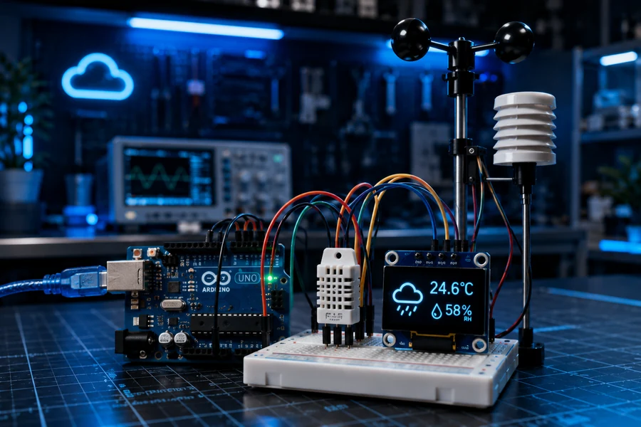
What you will learn
- How to wire a DHT22 temperature and humidity sensor.
- How to connect an I2C OLED display using SDA and SCL.
- How to install the Adafruit DHT, GFX, and SSD1306 libraries.
- How to print live readings to the Serial Monitor.
- How to troubleshoot blank displays, failed readings, and unstable breadboard wiring.
Important: The OLED uses I2C. On the Arduino Uno, SDA is A4 and SCL is A5. Do not connect them to random digital pins unless you rewrite the display setup for another board.
Parts Needed
| Part | Purpose | Affiliate-ready link |
|---|---|---|
| Arduino Uno | Main controller that reads the sensor and drives the OLED display. | Arduino Uno on Amazon |
| DHT22 / AM2302 Sensor | Measures temperature and humidity with better accuracy than a DHT11. | DHT22 sensor on Amazon |
| 0.96 inch I2C OLED Display | Shows live readings without needing a laptop connected. | SSD1306 OLED display |
| Breadboard | Makes the sensor and display wiring clean and removable. | Breadboard options |
| 10k Resistor | Optional pull-up resistor between DHT22 VCC and DATA if your sensor module does not include one. | Resistor kit |
| Jumper Wires | Connects the Arduino, breadboard, sensor, and display. | Jumper wires |
Detailed Wiring Guide
Wire the OLED first, then wire the DHT22. That keeps the build easier to test. After the OLED lights up, add the sensor and confirm the readings in the Serial Monitor.
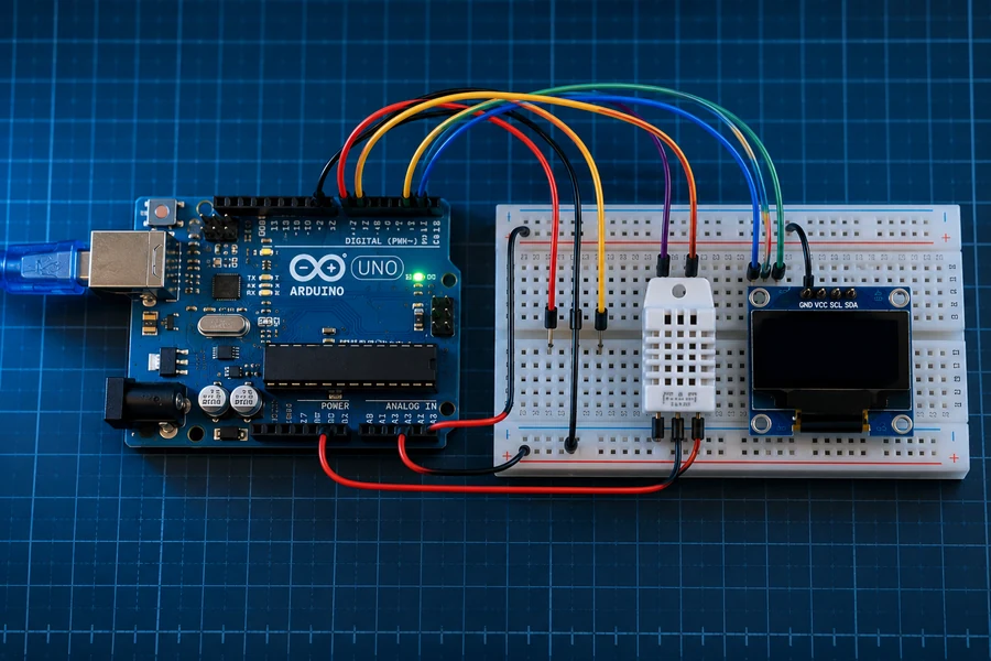
Full wiring overview
Use this image before plugging in wires. Match the display, sensor, power, and ground lines one connection at a time.
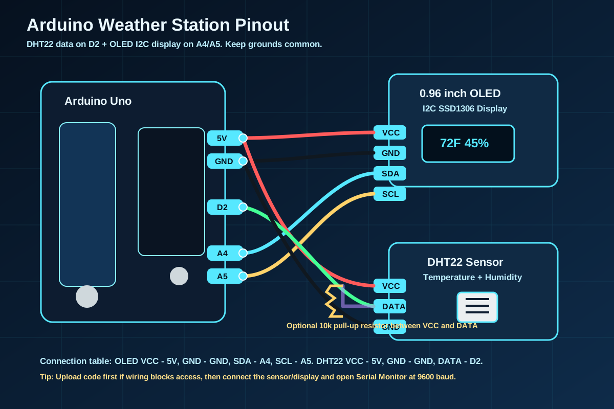
Pinout reference
This SVG shows the exact Arduino Uno pin mapping: OLED SDA to A4, OLED SCL to A5, and DHT22 DATA to D2.
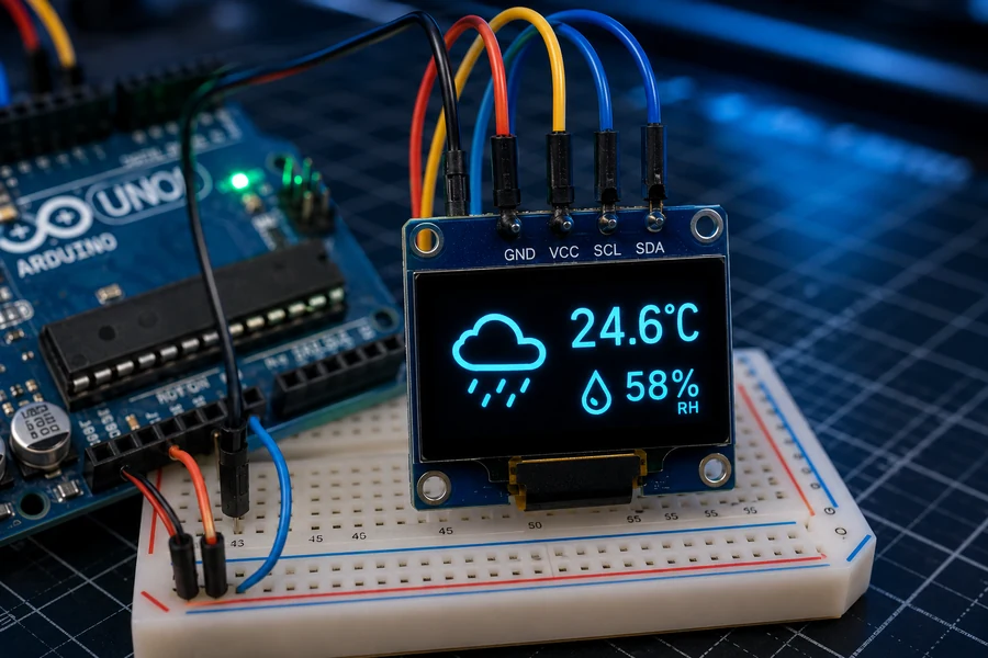
Close-up 1: OLED Display
Connect OLED VCC to 5V, GND to GND, SDA to A4, and SCL to A5. If the screen stays blank, check the I2C address.
Close-up 2: DHT22 Sensor
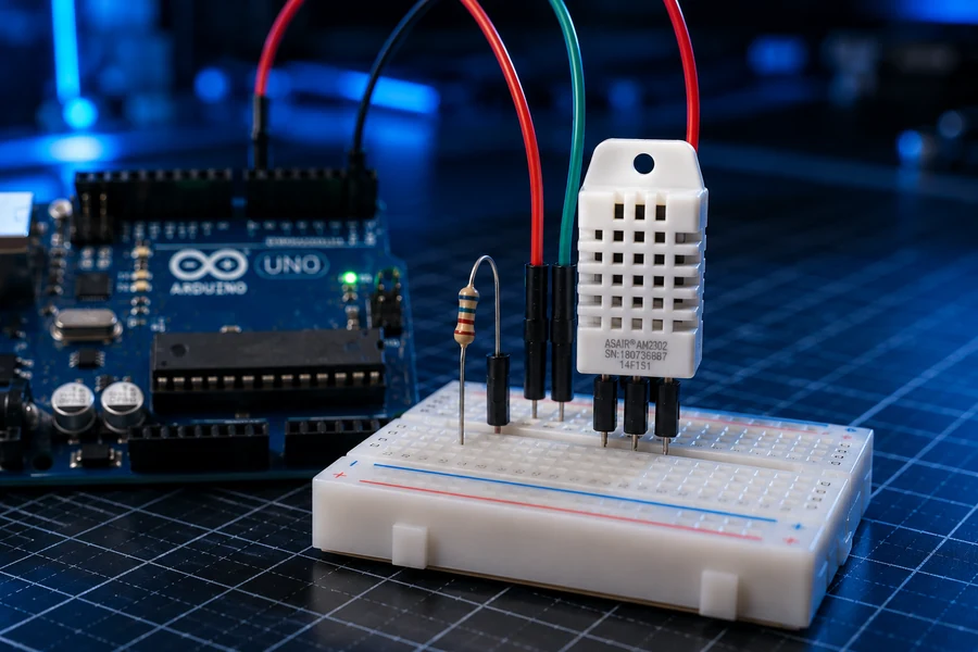
Connect VCC to 5V, GND to GND, and DATA to D2. Add a 10k pull-up resistor between VCC and DATA if your bare sensor needs it.
Pin Mapping Table
| Component Pin | Arduino Pin | Wire Color Suggestion | Notes |
|---|---|---|---|
| OLED VCC | 5V | Red | Most SSD1306 modules work from 3.3V to 5V, but check your module label. |
| OLED GND | GND | Black | Display ground must share Arduino ground. |
| OLED SDA | A4 | Blue | I2C data line on Arduino Uno. |
| OLED SCL | A5 | Yellow | I2C clock line on Arduino Uno. |
| DHT22 VCC | 5V | Red | Use 5V for simple Uno builds. |
| DHT22 DATA | D2 | Green | The code uses digital pin 2. |
| DHT22 GND | GND | Black | Do not skip the ground wire. |
| 10k resistor | Between VCC and DATA | Purple/Yellow | Optional for many breakout modules, required for many bare sensors. |
Arduino IDE Install Instructions
1. Install the required libraries
- Open the Arduino IDE.
- Go to Sketch > Include Library > Manage Libraries.
- Search for DHT sensor library by Adafruit and install it.
- Install Adafruit Unified Sensor if the IDE asks for it.
- Search for Adafruit SSD1306 and install it.
- Search for Adafruit GFX Library and install it.
2. Select the board and port
- Connect the Arduino Uno with a USB cable.
- Go to Tools > Board and select Arduino Uno.
- Go to Tools > Port and choose the COM port that appears when the Arduino is plugged in.
- Upload the code below.
- Open Tools > Serial Monitor and set the speed to 9600 baud.
Build Steps
- Place the Arduino Uno beside the breadboard so the wires do not stretch across the table.
- Connect the breadboard ground rail to Arduino GND.
- Connect the breadboard positive rail to Arduino 5V.
- Plug the OLED display into the breadboard or connect it directly with jumper wires.
- Wire OLED VCC to 5V, GND to GND, SDA to A4, and SCL to A5.
- Plug the DHT22 into the breadboard with the front grille facing you.
- Wire DHT22 VCC to 5V, DATA to Arduino D2, and GND to GND.
- If you are using a bare DHT22 sensor, place a 10k resistor between VCC and DATA.
- Upload the code and watch the OLED display. The first reading may take a couple seconds.
- Open the Serial Monitor at 9600 baud and confirm that temperature and humidity are printing repeatedly.
Good build habit: Test one section at a time. If the OLED does not work, fix that first before adding the DHT22. If the sensor does not work, verify the Serial Monitor before blaming the display.
Full Arduino Code
This sketch reads the DHT22, prints Celsius, Fahrenheit, and humidity to the Serial Monitor, then displays Fahrenheit and humidity on the OLED.
#include <Wire.h>
#include <Adafruit_GFX.h>
#include <Adafruit_SSD1306.h>
#include <DHT.h>

#define SCREEN_WIDTH 128
#define SCREEN_HEIGHT 64
#define OLED_RESET -1
#define OLED_ADDRESS 0x3C

#define DHTPIN 2
#define DHTTYPE DHT22

DHT dht(DHTPIN, DHTTYPE);
Adafruit_SSD1306 display(SCREEN_WIDTH, SCREEN_HEIGHT, &Wire, OLED_RESET);

void setup() {
  Serial.begin(9600);
  dht.begin();

  if (!display.begin(SSD1306_SWITCHCAPVCC, OLED_ADDRESS)) {
    Serial.println(F("OLED display not found. Check wiring or I2C address."));
    while (true);
  }

  display.clearDisplay();
  display.setTextColor(SSD1306_WHITE);
  display.setTextSize(1);
  display.setCursor(0, 0);
  display.println("WolfieWeb Weather");
  display.println("Starting sensor...");
  display.display();
  delay(2000);
}

void loop() {
  float humidity = dht.readHumidity();
  float tempC = dht.readTemperature();
  float tempF = dht.readTemperature(true);

  if (isnan(humidity) || isnan(tempC) || isnan(tempF)) {
    Serial.println(F("Failed to read from DHT22. Check VCC, DATA, GND, and pull-up resistor."));
    display.clearDisplay();
    display.setTextSize(1);
    display.setCursor(0, 0);
    display.println("Sensor Error");
    display.println("Check DHT22 wiring");
    display.display();
    delay(2000);
    return;
  }

  Serial.print(F("Humidity: "));
  Serial.print(humidity);
  Serial.print(F("%  Temp: "));
  Serial.print(tempC);
  Serial.print(F("C / "));
  Serial.print(tempF);
  Serial.println(F("F"));

  display.clearDisplay();
  display.setTextColor(SSD1306_WHITE);
  display.setTextSize(1);
  display.setCursor(0, 0);
  display.println("WolfieWeb Weather");
  display.drawLine(0, 12, 127, 12, SSD1306_WHITE);

  display.setTextSize(2);
  display.setCursor(0, 20);
  display.print(tempF, 1);
  display.println(" F");

  display.setTextSize(2);
  display.setCursor(0, 44);
  display.print(humidity, 1);
  display.println(" %");

  display.display();
  delay(2000);
}
Serial Monitor Testing
How to read the output
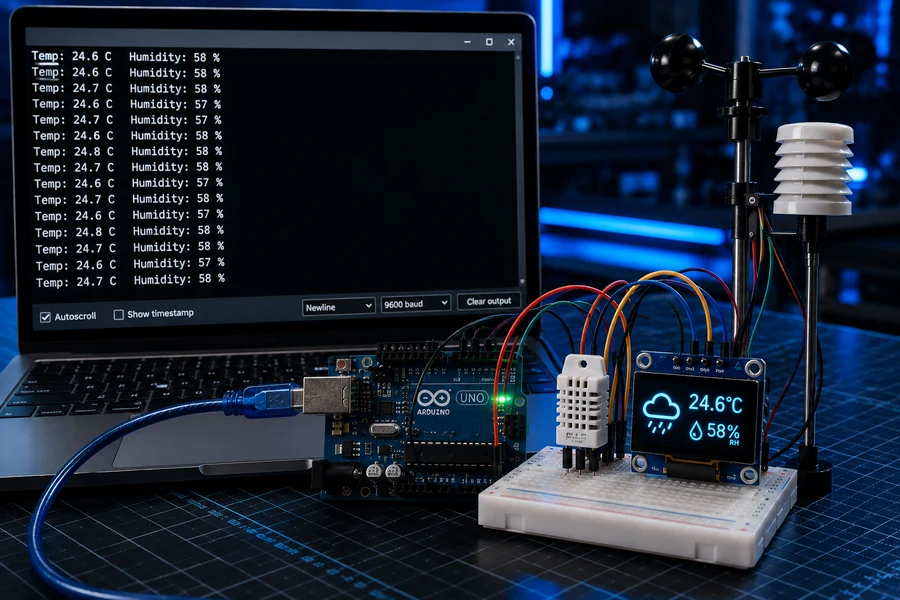
After the sketch uploads, open the Serial Monitor and set it to 9600 baud. You should see a repeating line with humidity, Celsius, and Fahrenheit. If the OLED is blank but the Serial Monitor works, the sensor is fine and the problem is likely the OLED wiring or I2C address.
If the Serial Monitor says the sensor failed, do not keep changing the code randomly. Check the DHT22 pin order, make sure DATA really goes to D2, and add the 10k pull-up resistor if needed.
Troubleshooting
OLED screen is blank
Check VCC, GND, SDA, and SCL. On Arduino Uno, SDA is A4 and SCL is A5. Some OLED modules use I2C address 0x3D instead of 0x3C. Change OLED_ADDRESS in the code if needed.
DHT22 reads NaN or failed
The sensor data pin may be in the wrong row, the sensor may need a pull-up resistor, or the pin order may not match your module. Confirm DATA goes to D2 and that the ground is shared.
Temperature looks wrong
Make sure you are reading Fahrenheit or Celsius intentionally. The code prints both to Serial Monitor but displays Fahrenheit on the OLED.
Readings update slowly
That is normal. DHT22 sensors are not meant to update extremely fast. A 2-second delay is safe and stable.
Upload fails
Select the correct board and port. Try a known-good USB data cable. Some cheap cables only charge and cannot upload sketches.
Display flickers
Keep wires short and seated firmly. Loose breadboard connections can make the display reset or flicker.
Related Build Videos
Use these popup videos as support: a full DHT22/OLED weather display build, an SSD1306 OLED display setup, and a DHT22 sensor wiring/coding walkthrough.
What You Learned
- You wired a DHT22 sensor to an Arduino digital pin.
- You connected an SSD1306 OLED display using I2C.
- You installed Arduino libraries the right way.
- You used the Serial Monitor as a real debugging tool.
- You built a standalone display project that can run without your laptop after upload.
Coming Next
Arduino GPS Tracker
Serial GPS data, latitude/longitude reading, location logging, and portable power.
Arduino Smart Irrigation
Soil moisture sensing, relay control, pump protection, and automation logic.
Arduino IoT Dashboard
Move from local readings to wireless data dashboards and remote monitoring.
Share This Arduino Weather Station Build
Use the buttons below to share this tutorial or copy the link for later.
Ready for the next build?
Save this weather station tutorial, then head back to WolfieWeb or the Arduino tutorial hub for more projects.